
Selecting the right geared motor requires evaluating your specific application’s torque, speed, efficiency, and dimensional constraints to match them with planetary, spur, worm, flat, or helical gearing layouts. Imagine designing a high-precision medical dosing pump or an automated conveyor system, only to discover during field testing that your assembly cannot deliver enough startup torque. This bottleneck forces you to run the motor at its absolute thermal limits, causing rapid mechanical wear, catastrophic torque loss, and ultimately, expensive line shutdowns. Fortunately, integrating high-quality, pre-engineered geared motors directly resolves these mechanical pain points by combining an electric motor with an optimized speed reducer in a single compact package.
What are the basics of industrial geared motors?
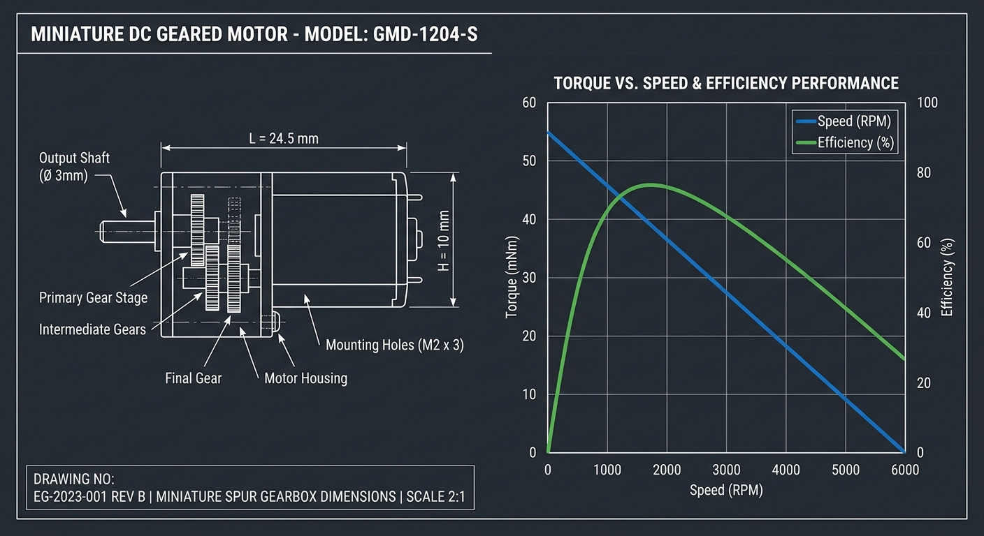
Industrial geared motors are integrated electro-mechanical units that combine an electric motor with an enclosed gear train to reduce rotational speed while multiplying output torque. By securing these components within a single housing, these engineered geared motors deliver highly predictable power transmission without the bulk of separate parts. This layout ensures optimal performance.
What is the fundamental anatomy of a geared motor?
At its core, the system consists of a rotor-driven motor shaft connected to a series of interlocking gears. This physical coupling forces the output shaft to rotate at a fraction of the motor’s raw speed. Here is the thing: the physical scaling of gears allows you to scale up the mechanical work without upgrading to a larger, more power-hungry electric motor.
To protect this delicate assembly from harsh operating environments, manufacturers use robust aluminum or zinc alloy casings. Inside, you will find several high-quality elements designed to withstand heavy abuse:
- Hardened steel or brass gears for minimal wear.
- Deep groove ball bearings to handle axial forces.
- Synthetic lubricants that reduce operating temperature.
Why integrated design trumps separate components?
Choosing a factory-assembled integrated drive system eliminates the tedious alignment and mounting tasks associated with discrete parts. If you attempt to couple a standard motor to a separate gearbox yourself, even microscopic shaft misalignment can cause rapid bearing failure. But wait, there’s more: integrated designs guarantee that the gear teeth mesh with absolute precision right out of the box.
Key Takeaway: Utilizing factory-integrated gearboxes maximizes drive efficiency, reduces footprint, and eliminates alignment risks, saving your team hours of engineering overhead.
| Design Parameter | Integrated Geared Motor | Discrete Coupled Setup | |
|---|---|---|---|
| Assembly Time | Zero (Ready-to-install) | High (Requires alignment) | |
| Misalignment Risk | None | High | |
| Envelope Volume | Ultra-Compact | Bulky | |
| Overload Capacity | Factory-Optimized | Variable |
This comparison demonstrates how integrated structural units outperform discrete component setups across all key operational metrics.
Why choose miniature planetary geared motors?
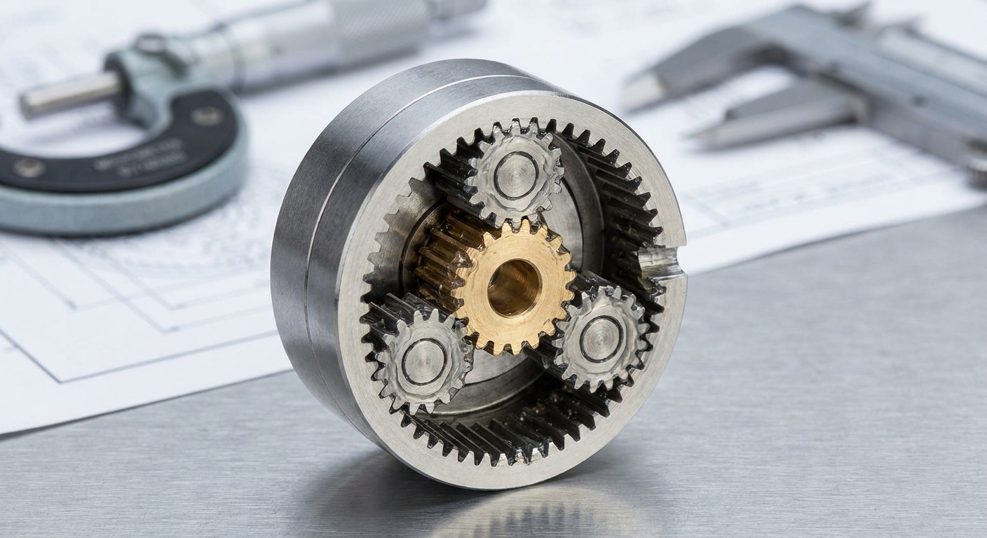
You should choose miniature planetary geared motors when your B2B application requires maximum torque density and minimal backlash within a highly restricted physical envelope. These high-density geared motors distribute mechanical stress equally across multiple planet gears, preventing premature gear failure under heavy shock loads.
How do planetary systems deliver maximum torque?
Planetary gear systems utilize a central sun gear that drives multiple outer planet gears riding inside an outer ring gear. This multi-point contact distributes the input load symmetrically across the gear teeth. Let’s dive in: because the torque is shared among several mesh points, these units handle much higher loads than other designs of equivalent size.
This load sharing dramatically increases mechanical stiffness and fatigue life. Let’s look at the primary structural benefits:
- Symmetrical load distribution prevents shaft bending.
- High power transmission efficiency up to 95%.
- Extremely compact inline cylindrical shape.
Are planetary drives ideal for precision uses?
Precision medical devices and robotic arms require minimal backlash to prevent positional errors during start-stop cycles. Planetary designs excel here because the tight tolerances between the sun, planet, and ring gears limit play to mere arc-minutes. Why does this matter? Any positioning errors in applications like surgical robots or precision dosing systems could compromise the entire process.
Key Takeaway: Miniature planetary drives offer the highest torque capacity per unit volume, making them the ultimate choice for high-precision, low-backlash industrial equipment.
| Technical Parameter | Specification / Range | |
|---|---|---|
| Typical Diameter | 12mm – 38mm | |
| Efficiency Rating | 90% – 95% | |
| Torque Capabilities | High to Ultra-High | |
| Primary Advantage | Outstanding torque density & low backlash | |
| Best Applications | Robotics, medical devices, precision dosing |
This engineering table highlights the superior performance metrics that planetary drives deliver to precision automation architectures.
When do compact spur geared motors perform best?
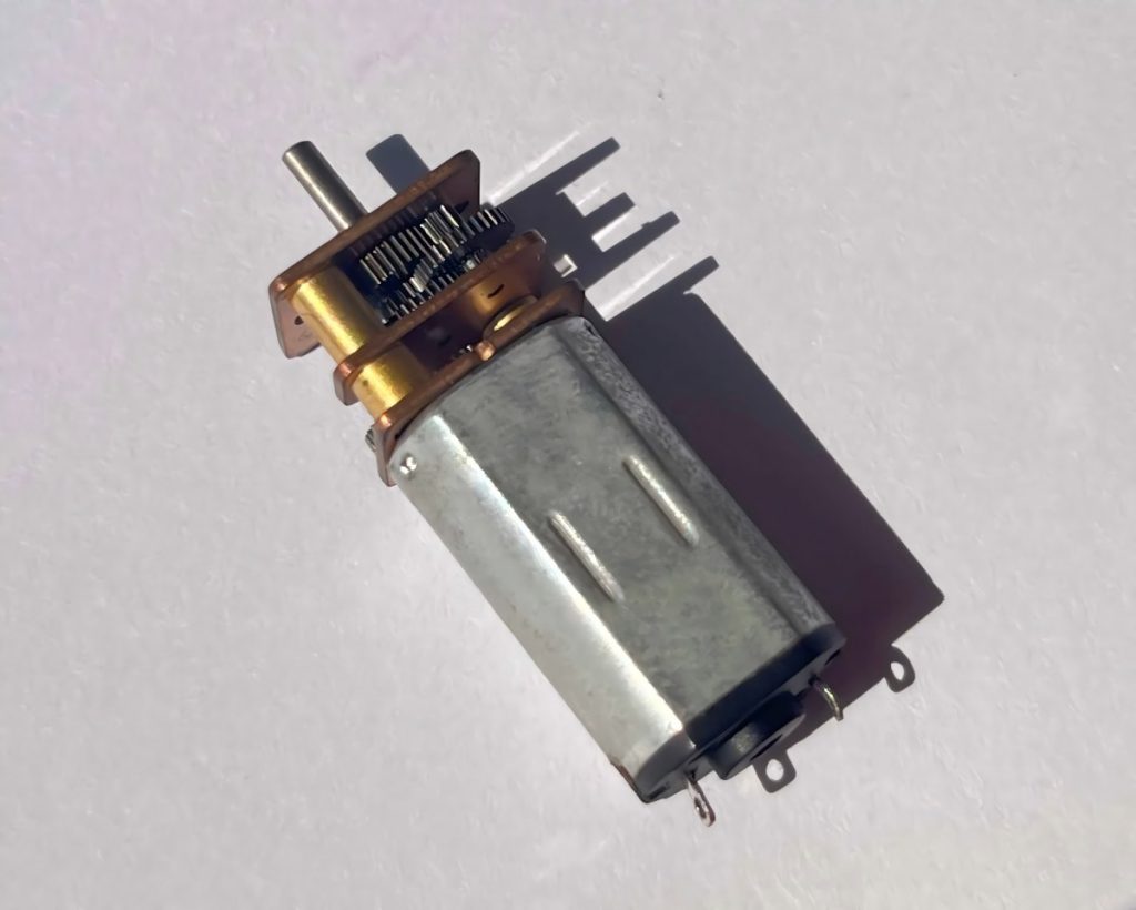
Compact spur geared motors perform best in cost-sensitive applications that operate at low-to-moderate speeds and require straightforward parallel-shaft speed reduction. These dependable geared motors employ straight-cut gears to transfer power with high efficiency and lower manufacturing costs. They are highly valued by OEMs.
Are spur gears the most cost-effective option?
For high-volume production runs, spur gearing represents the most economical mechanical drive layout available. The simple straight-tooth design is easy to manufacture and requires fewer steps during fabrication. Here is the thing: lower production complexity translates directly into major cost savings for your engineering project.
Moreover, the low friction loss of spur configurations keeps energy bills low. This efficiency yields outstanding benefits:
- Minimized manufacturing and component procurement costs.
- Simple parallel-shaft physical configuration.
- Lower heat dissipation requirements.
What limits in noise and load should you expect?
Because spur gear teeth engage along a single contact line all at once, they produce audible noise at high rotational speeds. Additionally, they cannot match the high torque capacity of planetary gearheads due to concentrated tooth stress. But wait, there’s more: using them in intermittent-duty applications like locks or dispensers completely bypasses these speed and noise limitations.
Key Takeaway: Spur gearboxes offer a highly reliable, cost-optimized drive solution for non-continuous, lower-speed applications where budget efficiency is a priority.
| Technical Parameter | Specification / Range | |
|---|---|---|
| Typical Diameter | 12mm – 50mm | |
| Efficiency Rating | 80% – 88% | |
| Torque Capabilities | Low to Moderate | |
| Primary Advantage | Highly cost-effective and structurally simple | |
| Best Applications | Vending machines, sanitary dispensers, smart locks |
The data above outlines how spur gearing remains the industry standard for cost-effective, straightforward motion applications.
How do self-locking worm geared motors work?

Self-locking worm geared motors work by utilizing a threaded screw shaft that drives a perpendicular gear wheel, creating high sliding friction that prevents the load from back-driving the motor. These highly secure geared motors deliver robust right-angle power transmission while acting as an inherent safety brake. They are widely used in lifting systems.
Can worm gearing eliminate external brakes?
The geometry of the worm screw prevents the output wheel from turning the input shaft, ensuring absolute locking when power is cut. This physical friction threshold eliminates the need for expensive electromechanical braking systems. Why does this matter? You can drastically simplify your control electronics and save valuable bill-of-materials space by relying on mechanical physics.
This self-locking capability is a massive advantage in safety-critical situations. Typical mechanical features include:
- Bronze worm wheels that reduce wear on the steel screw.
- Heavy cast-aluminum enclosures for thermal management.
- Massive single-stage reduction ratios.
What systems benefit from right-angle reduction?
Systems like automated gates, material hoists, and vertical dampers require a compact right-angle layout to fit within thin structural cavities. The perpendicular shaft orientation allows the motor body to lie flush against mounting walls. Let’s dive in: this spatial advantage makes them highly versatile for tight, angular spaces.
Key Takeaway: Worm-geared configurations provide built-in safety through self-locking mechanics and high single-stage reduction, removing the cost of auxiliary brakes.
| Technical Parameter | Specification / Range | |
|---|---|---|
| Output Shaft Angle | 90-Degree (Right-Angle) | |
| Efficiency Rating | 50% – 75% (due to sliding friction) | |
| Torque Capabilities | Moderate to High | |
| Primary Advantage | Self-locking capability & high reduction ratios | |
| Best Applications | Barriers, conveyors, electric valves, hoists |
This engineering table highlights why worm gear configurations are chosen for high-reduction, self-locking right-angle installations.
Where are space-saving flat geared motors used?
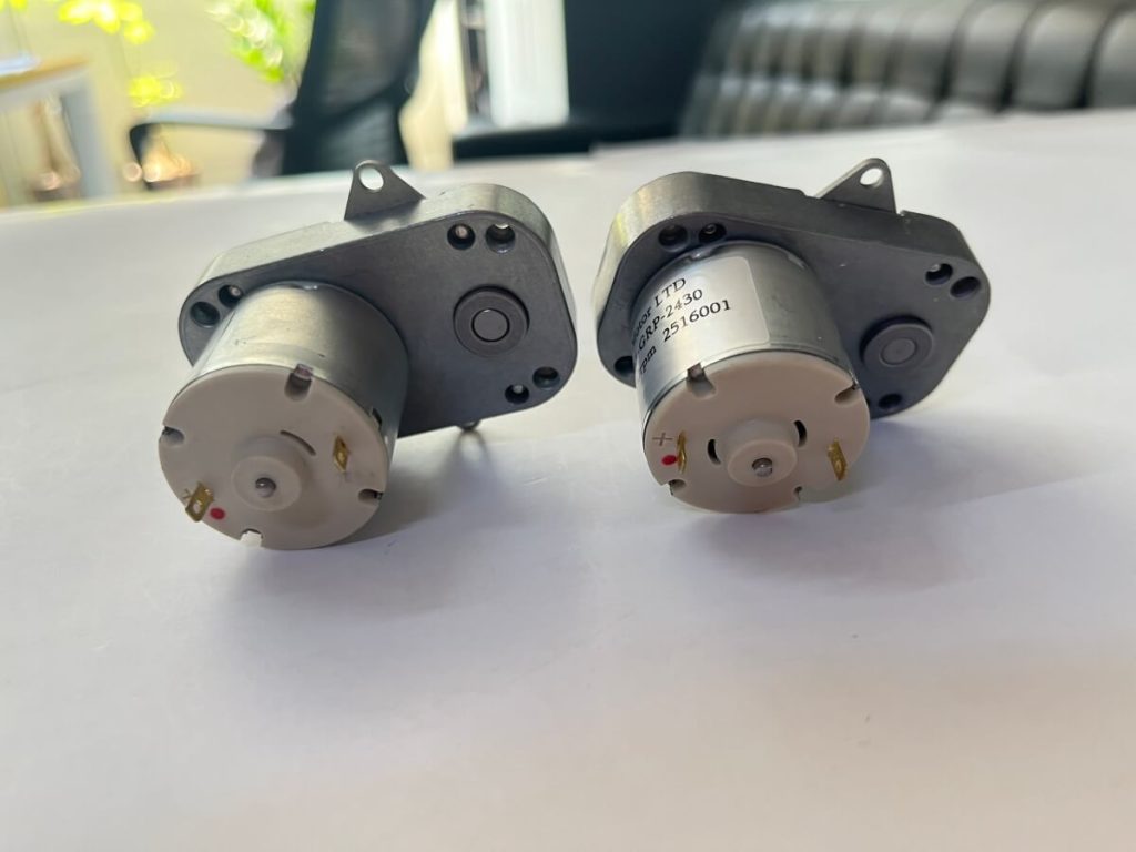
Space-saving flat geared motors are used in applications with strict physical depth limitations, such as commercial appliances, automated feeders, and slim actuators. These low-profile geared motors mount parallel to the driven shaft, allowing them to fit into narrow enclosures. This flat-pack design is ideal for space-constrained designs.
How does the flat design solve tight constraints?
By arranging the gearbox stages side-by-side rather than inline, the total longitudinal profile of the assembly is dramatically shortened. This flat configuration allows engineers to reduce the depth of their equipment enclosures. Here is the thing: a slim design lets you reclaim precious cabinet space for other system components or electronics.
This parallel-shaft arrangement is extremely robust under radial loads. Notable mechanical benefits include:
- An ultra-slim, space-optimizing housing profile.
- Dual output shaft options for bilateral drive applications.
- High radial load-bearing capacity due to wide gear spans.
What heavy-duty systems use flat gearboxes?
Many B2B systems like commercial barbecue rotisseries, automated pellet stoves, and agricultural feeding lines rely on these slim drives. Their wide gear faces allow them to deliver substantial continuous torque despite their flat appearance. But wait, there’s more: they perform beautifully under continuous, high-torque operations where standard inline motors would protrude awkwardly.
Key Takeaway: Flat-profile gearboxes are the ideal solution for high-reduction parallel-shaft applications that must slide into narrow physical spaces.
| Technical Parameter | Specification / Range | |
|---|---|---|
| Profile Depth | Ultra-Slim / Flat Packaging | |
| Efficiency Rating | 75% – 85% | |
| Torque Capabilities | Moderate to High | |
| Primary Advantage | Parallel-shaft spatial optimization | |
| Best Applications | BBQ grills, livestock feeders, slim actuators |
These operational parameters show how flat-profile configurations solve severe depth limitations without sacrificing torque output.
Why integrate brushless DC geared motors today?
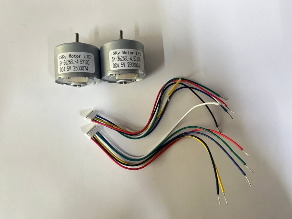
You should integrate brushless DC geared motors today to achieve maintenance-free longevity, quiet operation, and exceptional electronic speed control. These premium geared motors eliminate physical brush wear, preventing sparking and electromagnetic interference. This makes them perfect for sensitive cleanroom environments.
What makes BLDC essential for long-life systems?
Traditional brushed motors suffer from mechanical friction that eventually destroys the carbon brushes over time. Because brushless technology removes this physical contact, the service life of the motor is limited only by its high-quality ball bearings. Why does this matter? A motor that lasts over 10,000 hours cuts your field service costs and warranty claims down to virtually zero.
Eliminating brushes also removes sparking and mechanical carbon dust. This makes brushless drives ideal for demanding systems:
- Continuous-duty medical pumps and respirators.
- Automated guided vehicles operating in dust-sensitive cleanrooms.
- Subsea or sealed oil-filled actuation systems.
How do brushless motors optimize efficiency?
Electronic driver circuits continually adjust the stator fields to match the rotor’s exact position, minimizing electrical waste. This highly efficient power transfer keeps operating temperatures low, preventing gearbox lubricant degradation. Let’s dive in: this thermal efficiency extends the life of the internal gears and seals.
Key Takeaway: Combining brushless motor technology with robust gearboxes yields an ultra-reliable, highly efficient, and virtually maintenance-free powertrain for high-duty-cycle industrial equipment.
| Technical Parameter | Specification / Range | |
|---|---|---|
| Commutation | Electronic (Brushless) | |
| Lifespan | > 10,000 Hours | |
| Efficiency Rating | 85% – 92% (Motor level) | |
| Primary Advantage | No brush wear, silent operation, precise control | |
| Best Applications | Medical pumps, AGVs, high-end smart home automation |
This engineering table illustrates how integrating brushless motors provides unmatched durability and operational efficiency for modern equipment.
How do high-efficiency helical geared motors help?
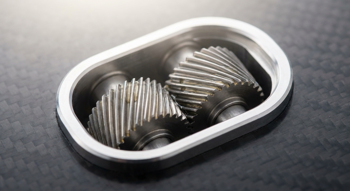
High-efficiency helical geared motors help by using angled teeth that engage gradually, which drastically reduces noise, minimizes vibration, and optimizes power transfer. These smooth-running geared motors distribute the mechanical load across a wider contact surface, allowing them to run quietly. This gradual engagement makes them perfect for quiet laboratory environments.
Why do angled teeth ensure smoother, quieter runs?
Unlike straight-cut spur gears that slap together upon contact, helical teeth slide together gradually along a helix path. This smooth rolling interaction prevents severe tooth impact, lowering overall mechanical noise below 45 decibels. But wait, there’s more: the massive reduction in vibration protects adjacent sensitive electronic sensors from physical distortion.
Smoother power delivery translates to incredibly stable rotational speed. Key advantages of this helical gear design include:
- Extremely low operating noise for clinical settings.
- Significantly reduced mechanical vibration.
- Higher shock load resistance under sudden stops.
Can helical systems substantially reduce waste?
Because helical teeth mesh with high rolling efficiency, very little energy is lost to heat or friction. This high conversion rate lowers your equipment’s power consumption and prevents heat buildup in continuous-run systems. Here is the thing: running cooler means your system lubricants maintain their viscosity, protecting critical parts from wear.
Key Takeaway: Helical gear configurations combine quiet, smooth tooth engagement with outstanding mechanical efficiency, protecting your drive from wear and minimizing thermal losses.
| Technical Parameter | Specification / Range | |
|---|---|---|
| Gear Tooth Style | Angled (Helical) | |
| Noise Level | Extremely Low (< 45 dB) | |
| Efficiency Rating | 90% – 95% | |
| Primary Advantage | Ultra-smooth power transmission and minimal noise | |
| Best Applications | Continuous mixers, printing equipment, cleanroom conveyors |
This engineering breakdown explains how helical gear designs minimize noise and energy losses under heavy continuous duty.
Which geared motors fit: inline or right-angle?
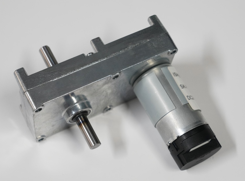
Choosing between inline and right-angle geared motors depends on whether your machine envelope favors coaxial length or minimal depth layout. These distinct geared motors are designed to optimize space and mounting configurations across diverse industrial chassis. Selecting the appropriate orientation prevents physical interference during system assembly.
When should you specify an inline shaft layout?
Inline configurations arrange the motor shaft and the output shaft along the exact same centerline. This straight configuration is highly efficient and perfectly suited for transferring pure axial pushing or pulling forces. Let’s dive in: when your machine design has plenty of longitudinal room, an inline setup is always the most efficient option.
This straight-through configuration delivers direct force with minimal wear. The typical design parameters include:
- Highly efficient energy transfer through straight-line gears.
- Excellent structural alignment for linear actuator shafts.
- Simpler physical mounting using standard flange faces.
Does a right-angle layout improve footprint?
Right-angle gearboxes direct the output shaft 90 degrees away from the motor axis, allowing the motor to sit flush against the machine wall. This clever packaging cuts the required installation depth down to a fraction of an inline unit. Why does this matter? You can fit powerful drive assemblies into tight recesses without modifying your external machine dimensions.
Key Takeaway: Select inline configurations for simple axial layouts and peak mechanical efficiency, but choose right-angle configurations when physical depth is extremely limited.
| Feature | Inline Configuration | Right-Angle Configuration | |
|---|---|---|---|
| Shaft Orientation | Coaxial / Parallel to Motor | 90-Degree perpendicular to Motor | |
| Space Strength | Lengthwise space allowance | Minimal depth space allowance | |
| Typical Gearing | Spur, Planetary, Helical | Worm, Bevel, Hypoid | |
| Typical Efficiency | 80% – 95% | 50% – 85% |
This comparison provides clear spatial guidance to help you select the ideal shaft layout for your equipment enclosure.
How do encoder-equipped geared motors add value?
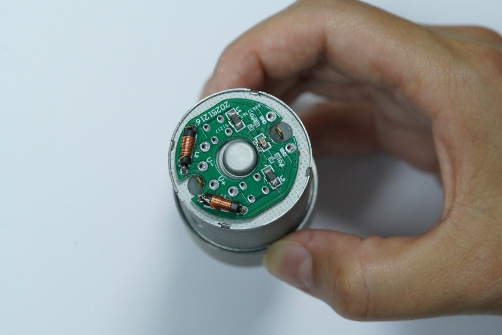
Encoder-equipped geared motors add value by providing real-time positional and speed feedback, turning a basic motor into an intelligent closed-loop actuator. These smart geared motors ensure that microcontrollers can monitor the exact rotation of the output shaft at all times. This feedback loop is essential for precise robotics and automation.
Why is precise position and speed feedback vital?
Without continuous physical feedback, an automated system operates blindly, unable to detect shaft slippage or mechanical blockages. Integrating a high-resolution encoder allows your controller to dynamically adjust voltage to maintain precise target velocities. Here is the thing: closed-loop monitoring ensures that your machinery behaves exactly as programmed, even under fluctuating torque loads.
This electronic feedback is crucial for safety and system diagnostic checks. Real-world feedback benefits include:
- Instant safety shutdown when an unexpected physical obstruction is met.
- Ultra-precise angular positioning down to tiny fractions of a degree.
- Real-time speed tracking to synchronize multiple conveyor lines.
How do Hall sensor encoders enhance smart loops?
Magnetic Hall-effect encoders utilize a multi-pole magnetic wheel mounted to the rear motor shaft to generate high-frequency electrical pulses. Because these dual-channel sensors detect physical magnetic poles, they are completely immune to dust and moisture contamination. But wait, there’s more: the dual-channel quadrature output allows your microcontroller to easily determine both speed and rotation direction.
Key Takeaway: Integrating robust magnetic encoders on geared drives turns basic motors into smart, resilient closed-loop systems, ensuring absolute control over velocity and position.
| Technical Parameter | Specification / Range | |
|---|---|---|
| Sensor Type | Dual-channel magnetic Hall encoder | |
| Feedback Output | Quadrature square-wave pulses | |
| Integration | Directly mounted to motor rear shaft | |
| Primary Advantage | Real-time speed and direction monitoring | |
| Best Applications | AGVs, access control barriers, medical pumps |
The engineering data shown above highlights how magnetic feedback systems maintain stable performance under harsh operating conditions.
Which custom geared motors suit your project?
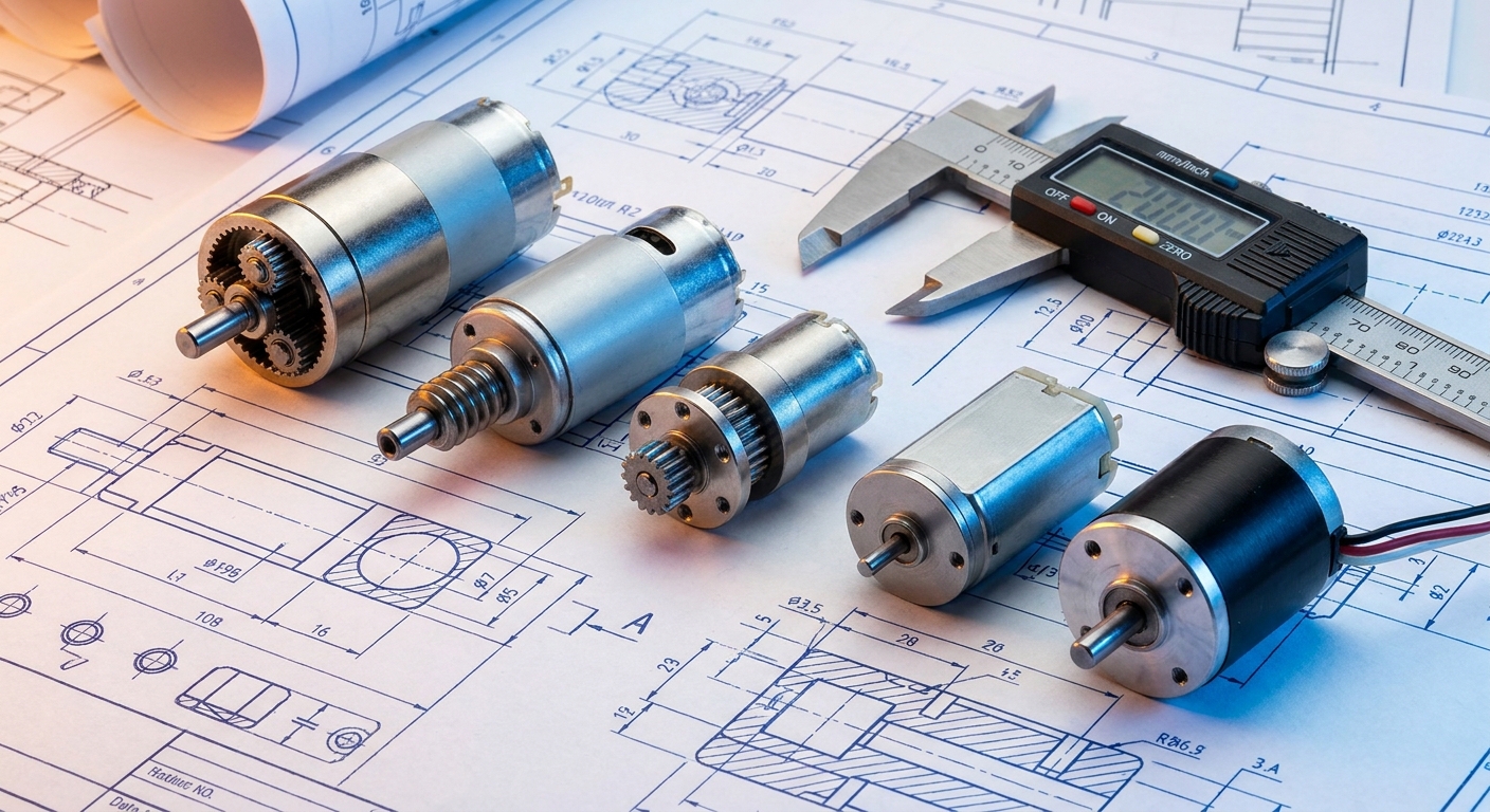
Finding which custom geared motors suit your project requires balancing nominal voltage, target output torque, speed, duty cycle, and mounting envelope with your specific performance goals. Tailoring these geared motors ensures optimal mechanical performance and prevents costly electrical failures. Our experienced engineers can customize every internal component to match your precise application requirements.
How to balance voltage, torque, and speed?
To prevent motor burnouts, you must define your nominal voltage and continuous operating torque before selecting any components. Standard battery-operated designs typically require 12V or 24V DC configurations to preserve power and efficiency. Why does this matter? Over-specifying your torque output leads to excessive battery drain, while under-specifying causes the gearbox to stall and overheat.
Working with an experienced manufacturing partner allows you to customize the winding and gear ratio to achieve the perfect operational balance. Consider these vital specification steps:
- Determine continuous and peak torque under actual loads.
- Measure maximum allowable speed under full mechanical load.
- Identify envelope restrictions and mounting shaft dimensions.
Frequently asked selection questions answered
Navigating the complex technical options during the design phase requires clear collaboration between your engineering team and the factory. Custom shaft flats, specialized wiring harnesses, and custom gear materials can all be engineered to suit your unique operating conditions. But wait, there’s more: getting the right configuration from the start prevents expensive redesigns and product delays.
Key Takeaway: Balancing voltage, torque, speed, and packaging constraints during the design phase with an experienced manufacturing partner avoids costly design revisions and ensures long-term field reliability.
| Sizing Step | Engineering Action Required | Goal / Target Outcome | |
|---|---|---|---|
| Step 1: Torque | Calculate nominal and peak operating loads | Avoid motor stalls and premature gear wear | |
| Step 2: Speed | Define target RPM under full load conditions | Maintain system throughput and cycle times | |
| Step 3: Space | Map out physical footprint and shaft layout | Ensure perfect integration into the enclosure | |
| Step 4: Custom | Request custom wiring and shaft modifications | Streamline your final factory assembly line |
This structured checklist guides engineering teams through the essential steps needed to qualify custom drive specifications.
Engineering Consultation & B2B Partnership
Partnering with an experienced, factory-direct manufacturer ensures you get the exact performance, lifetime, and cost balance required for your application. We solve your most complex powertrain problems—from severe spatial constraints and torque limitations to positional accuracy challenges. Our state-of-the-art facilities deliver highly customized, premium planetary, worm, and spur configurations built to your exact specifications. From initial prototype validation to high-volume mass production, we are committed to turning your ambitious engineering ideas into precise, reliable motion. To discuss your specific torque, speed, and dimensional requirements, contact us today to request a free engineering consultation and custom quotation.
Frequently Asked Questions
Can I get a custom shaft design, custom voltage, and specialized cable connectors for my OEM order?
Yes, full custom modification is highly supported for all volume orders. Factory-direct engineering teams regularly customize output shafts (including D-cuts, cross-holes, and keyways), tailor the motor windings to match your specific DC supply voltage, and integrate custom terminal plugs or wiring harnesses to streamline your final assembly line process.
What’s the best geared motor option for space-constrained, battery-powered smart padlocks?
A miniature spur or planetary geared motor with a high gear ratio is the absolute best option for this application. These layouts deliver outstanding holding torque to secure locking mechanisms while maintaining an ultra-small physical profile that preserves battery life through highly efficient, low-current operation.
How do I know if my commercial automation project requires a high-precision planetary gearbox or a cost-effective spur gearbox?
You must analyze your application’s radial load, backlash requirements, and operating duty cycle. If your system requires minimal backlash and must withstand high, continuous shock loads in a compact cylindrical space, specify a planetary drive; if cost reduction is your primary driver and the load is moderate and intermittent, opt for a spur gearbox.
Can I integrate dual-channel Hall encoders with both brushless DC (BLDC) and brushed DC geared motors?
Yes, magnetic Hall-effect encoders can be seamlessly integrated into both motor types. By mounting a multi-pole magnetic target disc on the rear motor shaft adjacent to a custom sensor PCB, you get robust, high-frequency quadrature square-wave feedback regardless of whether the underlying motor utilizes physical brushes or electronic commutation.
What’s the best method to evaluate the real-world duty cycle and peak torque load to prevent motor overheating in the field?
The most reliable method is conducting thermal-rise and current-draw testing under full mechanical load inside your prototype chassis. By measuring the motor’s actual current draw and housing temperature over an extended operating cycle, you can calculate the exact root-mean-square (RMS) torque and prevent thermal overload in the field.