
Choosing the right torque reduction gearbox for industrial equipment requires balancing input motor characteristics, dimensional constraints, and the target application’s specific torque and speed demands. When you design modern automated systems, encountering tight space envelopes can lead to catastrophic motor stalls and overheating if your mechanism lacks sufficient driving force. It is incredibly frustrating to watch high-value production machinery grind to a halt because a generic motor simply cannot handle the starting friction or varying load demands. Fortunately, integrating a high-performance gearbox motor provides an elegant, compact solution that scales up torque while dropping output speed to highly controllable levels. This comprehensive technical guide walks you through every major gear geometry, configuration choice, and engineering metric necessary to optimize your next power transmission design.
Why Choose a Miniature Gearbox Motor?
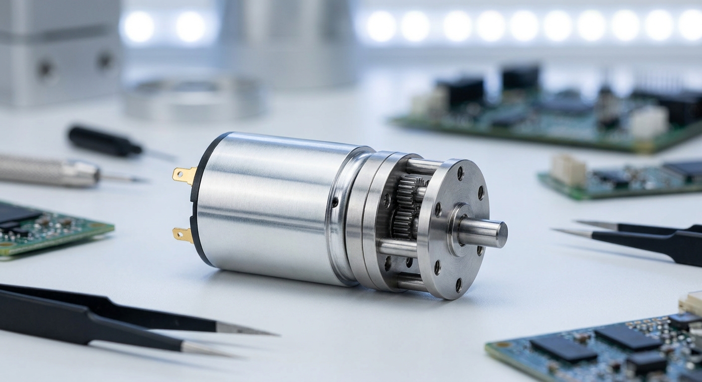
You should choose a miniature gearbox motor because it delivers outstanding power density, allowing you to install robust torque capability into highly restricted physical spaces. Standard raw motors often run at incredibly high speeds but possess very little starting torque, making them inefficient for direct-drive heavy mechanical loads. By combining a precision-engineered micro-gearhead directly onto the motor shaft, you instantly gain a mechanical advantage that resolves space-to-torque conflicts. This compact integration simplifies your mechanical designs, reduces assembly time, and eliminates the need for external pulleys or chains.
How does size impact efficiency?
Let’s face it: smaller machinery demands component miniaturization without any sacrifice in operating reliability. When you shrink the physical volume of a drive system, managing heat dissipation and structural rigidity becomes much more challenging. High-quality miniature gearheads address these concerns by utilizing advanced metallurgy and specialized synthetic lubricants.
- Miniaturization reduces overall system weight and structural loading.
- Optimized gear profiles minimize friction losses in the gear train.
- Precise housing design prevents oil leakage and dust ingress.
Are there mounting limitations?
You can mount these compact powerhouses in almost any orientation, which is crucial for complex robotic or medical assemblies. The rigid, pre-integrated design ensures that the internal gears remain perfectly aligned even under high vibrational stresses. Think about it: a misaligned motor-to-gearbox coupling can ruin your efficiency and destroy your system within hours. Buying a pre-assembled unit removes this risk entirely and keeps your operations running flawlessly.
Key Takeaway: Selecting a miniature gearbox motor guarantees optimized power density and hassle-free alignment in space-constrained applications.
| Feature / Metric | Standard Motor | Miniature Gearbox Motor | |
|---|---|---|---|
| Torque-to-Weight Ratio | Low | Extremely High | |
| Integration Complexity | High (Requires external coupling) | Minimal (Fully pre-assembled) | |
| Physical Footprint | Large / Bulky | Ultra-Compact |
Use this comparison table to quickly audit whether your current system layout can benefit from miniature power integration.
How Does a Gearbox Motor Maximize Torque?
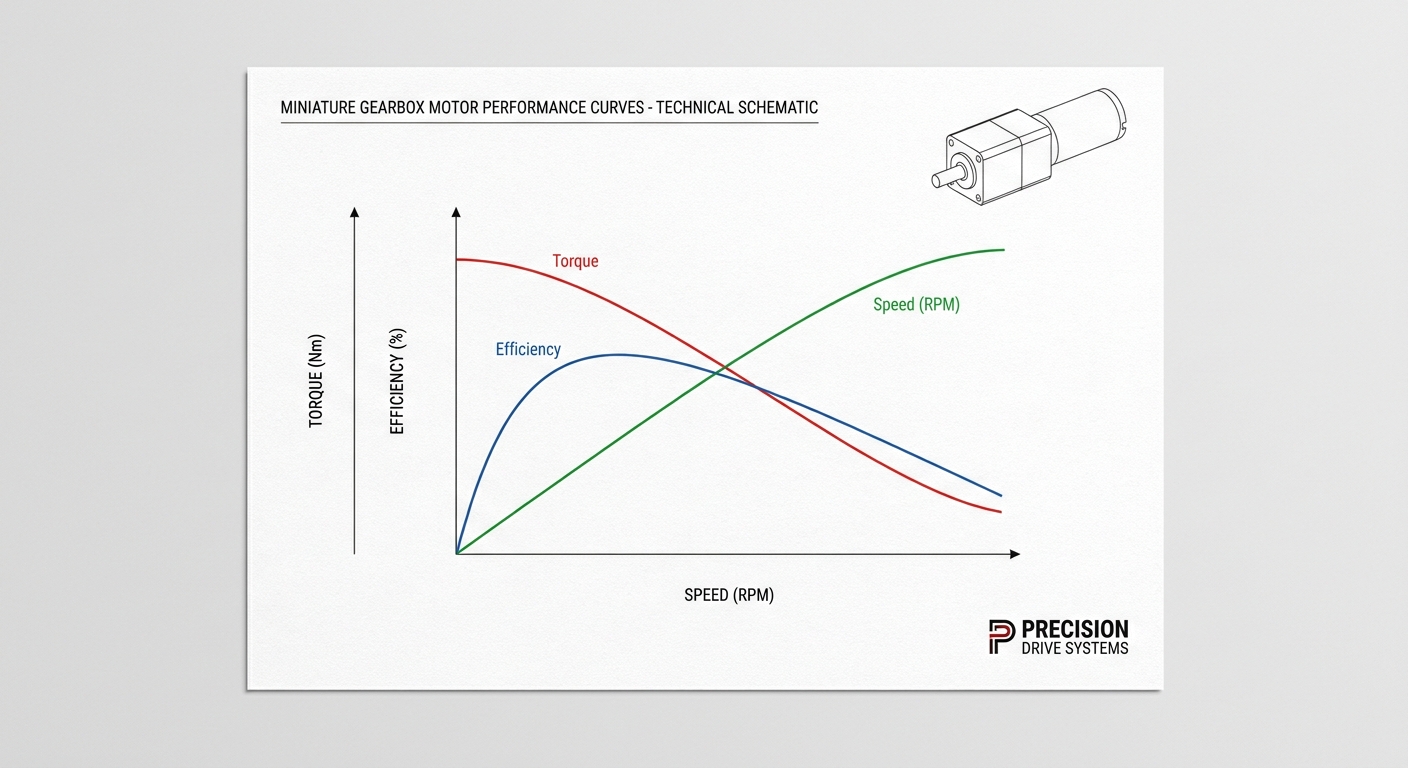
A gearbox motor maximizes torque by leveraging the fundamental principles of mechanical advantage, where reducing output speed proportionally multiplies the rotational force. The internal gear ratios act as a multiplier, taking the low torque of a high-speed motor and scaling it up through successive gear meshing stages. This mechanical multiplication allows you to drive heavy, high-inertia loads using a surprisingly small electrical motor. Consequently, your system operates with much lower electrical current demands during peak load conditions.
What is the role of the gear ratio?
The gear ratio determines exactly how much torque you will gain and how much rotational speed you will sacrifice in the process. For example, a 100:1 reduction ratio theoretically increases the output torque by a hundredfold while dropping the speed to one-hundredth of the input motor speed. The truth is: gear efficiency losses will slightly reduce this theoretical maximum torque output.
- High gear ratios provide immense holding and driving torque.
- Multiple gear stages allow you to fine-tune speed outputs.
- Precision teeth manufacturing ensures smooth, predictable torque transitions.
How does backlash affect performance?
When you reverse the direction of your motor, any tiny gap between the gear teeth manifests as play, known as backlash. In high-precision positioning applications, minimizing this backlash is absolutely paramount to achieving sub-millimeter accuracy. Here is the thing: if your gearbox has too much play, your automated system will overshoot or drift over time. Choosing high-precision metal gears keeps this mechanical backlash to an absolute minimum.
Key Takeaway: Torque multiplication is directly governed by gear ratios, but you must account for gear efficiency and backlash to preserve system accuracy.
| Metric | Low Gear Ratio (e.g., 5:1) | High Gear Ratio (e.g., 200:1) | |
|---|---|---|---|
| Output Torque | Moderate | Exceptionally High | |
| Output Speed | High | Low | |
| Typical Efficiency | ~90% – 95% | ~60% – 75% |
Evaluate these torque scaling tradeoffs to select the optimal gear ratio without over-stressing your electrical systems.
Which Gearbox Motor Architecture is Best?
The best gearbox motor architecture is highly dependent on your specific application requirements, balancing factors like physical space, budget, and physical load orientation. For highly demanding, high-torque applications with strict axial alignment, selecting a planetary gearbox motor stands out as the premium choice. However, alternative styles like worm and spur configurations offer specialized advantages in cost-effectiveness or spatial layouts. Understanding these fundamental mechanical differences allows you to choose the most reliable drive configuration.
What are the primary configurations?
There are three classic gear arrangements that dominate the industrial landscape, each serving distinct functional niches. You can choose inline configurations for simple linear layouts, or right-angle gearboxes to save depth in narrow enclosures. Think about it: picking the wrong mechanical layout will force you to redesign your entire structural chassis.
- Planetary setups distribute torque evenly among multiple gears.
- Worm drives offer a compact right-angle layout and self-locking safety features.
- Spur gears provide the most cost-effective and straightforward inline option.
How do you weigh performance vs. budget?
You must always balance high-end features against your overall production budget to maintain project feasibility. While planetary gearboxes offer the highest durability and power density, spur gearboxes might be completely adequate for low-load, intermittent operations. But wait, there’s more: over-specifying a gearbox can lead to unnecessary costs and excessive system weight. Analyzing your actual torque demands prevents you from paying for performance margins you do not need.
Key Takeaway: Align your choice of gearbox architecture with your physical space limits, load demands, and budgetary targets.
| Gearbox Architecture | Power Density | Cost Profile | Best Use Case | |
|---|---|---|---|---|
| Planetary | Outstanding | Premium | Robotics & High-Load Positioning | |
| Worm | Medium | Moderate | Conveyors & Elevators (Self-locking) | |
| Spur | Moderate | Economical | Low-Torque Dispensing & Toys |
Compare these three foundational architectures to establish the ideal balance of performance and cost for your device.
Why Use a Planetary Gearbox Motor?
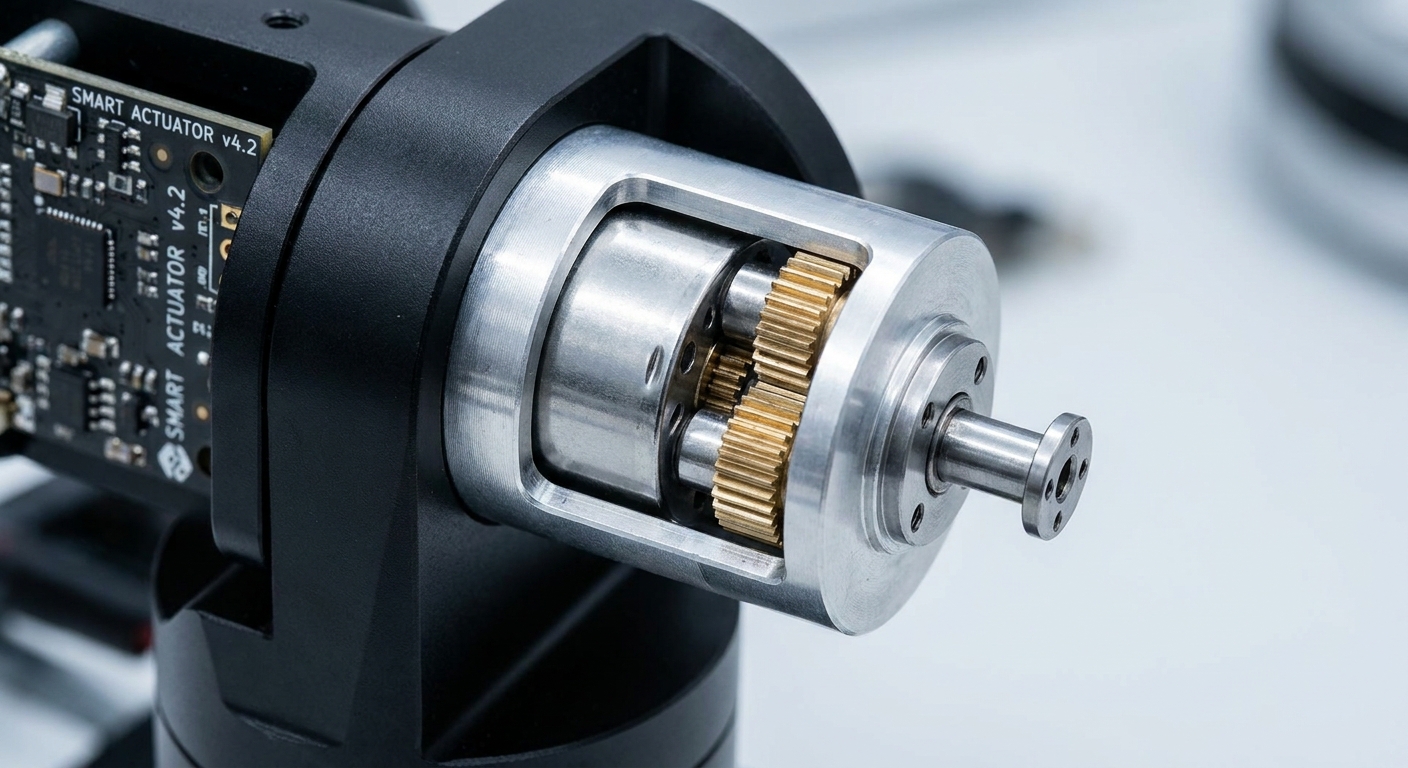
You should use a planetary gearbox motor because its unique load-sharing design delivers unmatched torque density and exceptional rotational precision within a very small footprint. In a planetary configuration, multiple planet gears engage with the central sun gear simultaneously to distribute the mechanical load evenly across multiple contact points. This design dramatically minimizes the internal stress on individual gear teeth, allowing the unit to handle high torque spikes safely. As a result, you get a highly durable drive that easily handles sudden stop-and-start industrial movements.
How does load distribution work?
Because the load is shared across multiple teeth, a planetary system achieves much higher torque capacity than a single-contact spur gear system of equivalent size. When you input power through the sun gear, the planetary gears revolve around it inside the outer ring gear to smoothly transfer rotation to the output shaft. The truth is: this balanced geometry naturally cancels out radial forces on the internal bearings.
- Balanced load distribution prevents shaft deflection and premature wear.
- Low internal friction levels keep operating temperatures cool under continuous duty.
- Multiple reduction stages can be stacked inline to multiply torque endlessly.
Is high precision guaranteed?
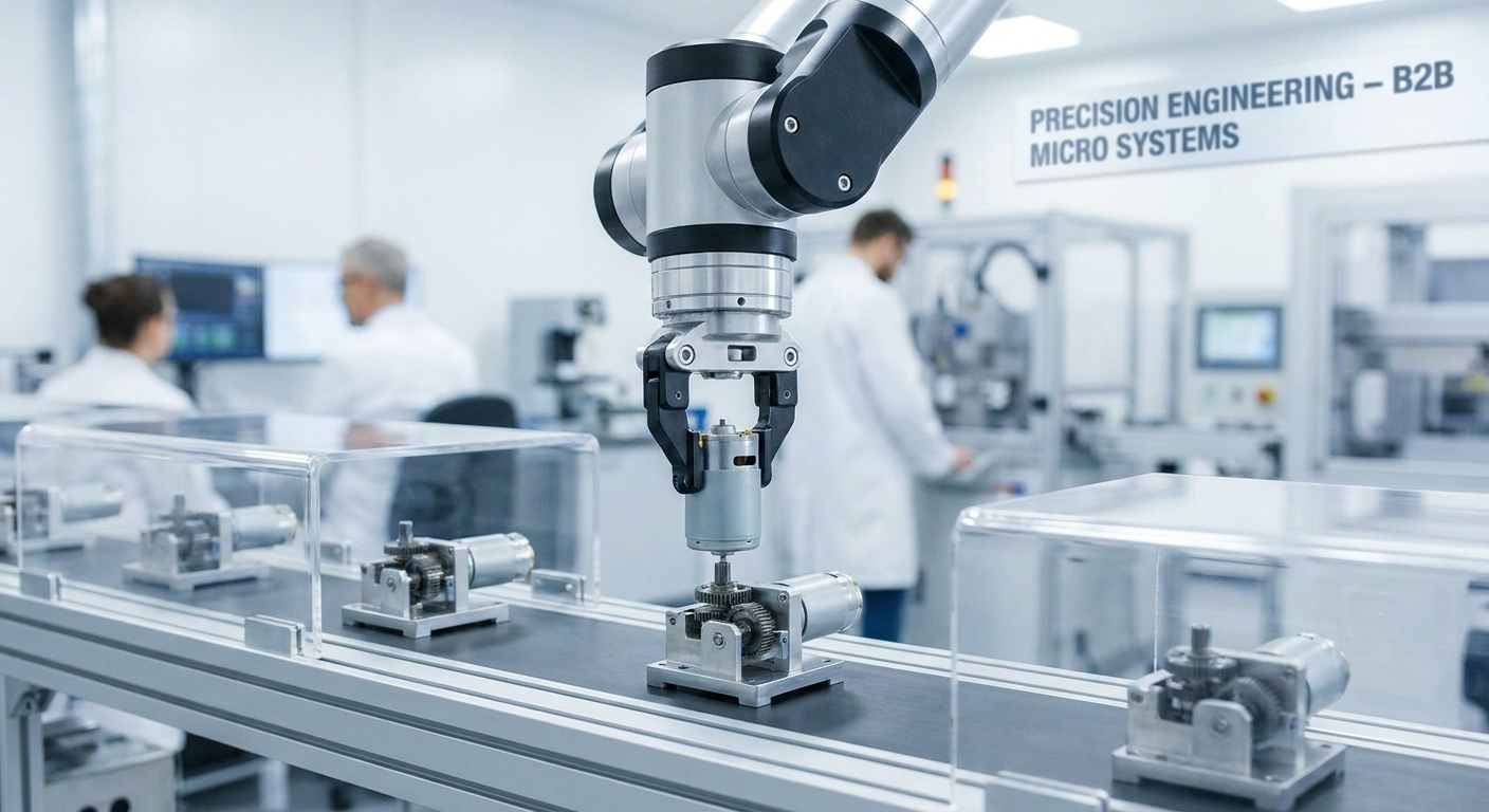
You will find that planetary systems exhibit incredibly low backlash, making them perfect for precise servo control. The tight manufacturing tolerances required for these components ensure highly repeatable positioning in automatic pick-and-place machinery. Let’s face it: if your robotic arm drifts even a millimeter, your entire production yield can suffer. Investing in high-quality planetary gearheads ensures that your systems hit their positional targets every single time.
Key Takeaway: Planetary gear systems are the gold standard for high-precision, high-torque industrial robotics and automation.
| Feature | Planetary Design Advantage | Operational Impact | |
|---|---|---|---|
| Load Distribution | Shared across 3 to 4 planet gears | Prevents wear, increases gear life span | |
| Backlash Rating | Extremely Low (< 1 degree) | Maximizes accuracy in precision robotics | |
| Efficiency Range | High (Typically 80% – 90%) | Conserves battery or mains electrical power |
Analyze these unique planetary advantages to determine if your application warrants the investment in high-precision gearheads.
When is a Worm Gearbox Motor Required?
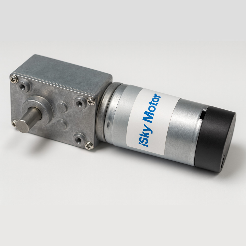
A worm gearbox motor is required when you need a right-angle drive configuration, massive single-stage speed reduction, or a reliable self-locking safety mechanism to prevent backdriving. Because the input worm screw drives a perpendicular output worm wheel, the force cannot easily flow backward through the gear train. This mechanical characteristic is incredibly valuable for applications like elevators, conveyors, and security gates where load slipping is a major hazard. By utilizing this physical property, you can often eliminate the need for costly external electronic braking systems.
Why is right-angle mounting useful?
Right-angle orientation allows you to run your motor parallel to your conveyor line or machine frame, saving vital workspace. If you are designing equipment that must sit flush against a wall or fit inside a shallow cabinet, this layout is ideal. Here is the thing: trying to fit an inline motor into a narrow panel is a recipe for design frustration.
- Perpendicular output shaft simplifies tight, side-by-side machine mounting.
- Compact gearbox housing integrates easily into conveyor roller frameworks.
- Direct-drive shaft coupling eliminates expensive external bevel gears.
What is the self-locking phenomenon?
When the lead angle of the worm screw is sufficiently small, the friction between the screw and the gear teeth prevents the gear from turning the screw. You can leverage this physical locking characteristic to support heavy vertical loads without relying on active electrical motor holding current. Best of all: this feature guarantees that your load remains perfectly in place even if the power cuts out completely. It protects your operators and delicate cargo from sudden, unexpected gravity drops.
Key Takeaway: Worm gearboxes excel in right-angle designs where self-locking safety and high single-stage reduction are mandatory.
| Parameter | Worm Gearbox Status | Mechanical Consequence | |
|---|---|---|---|
| Output Shaft Direction | 90-Degree Right-Angle | Saves longitudinal space along frames | |
| Backdrive Capability | Self-Locking (At high ratios) | Acts as a reliable secondary safety brake | |
| Acoustic Noise | Exceptionally Quiet | Ideal for medical and commercial settings |
Use this parameter overview to assess if right-angle self-locking gearboxes are suitable for your vertical lifting mechanisms.
How Does a Spur Gearbox Motor Compare?
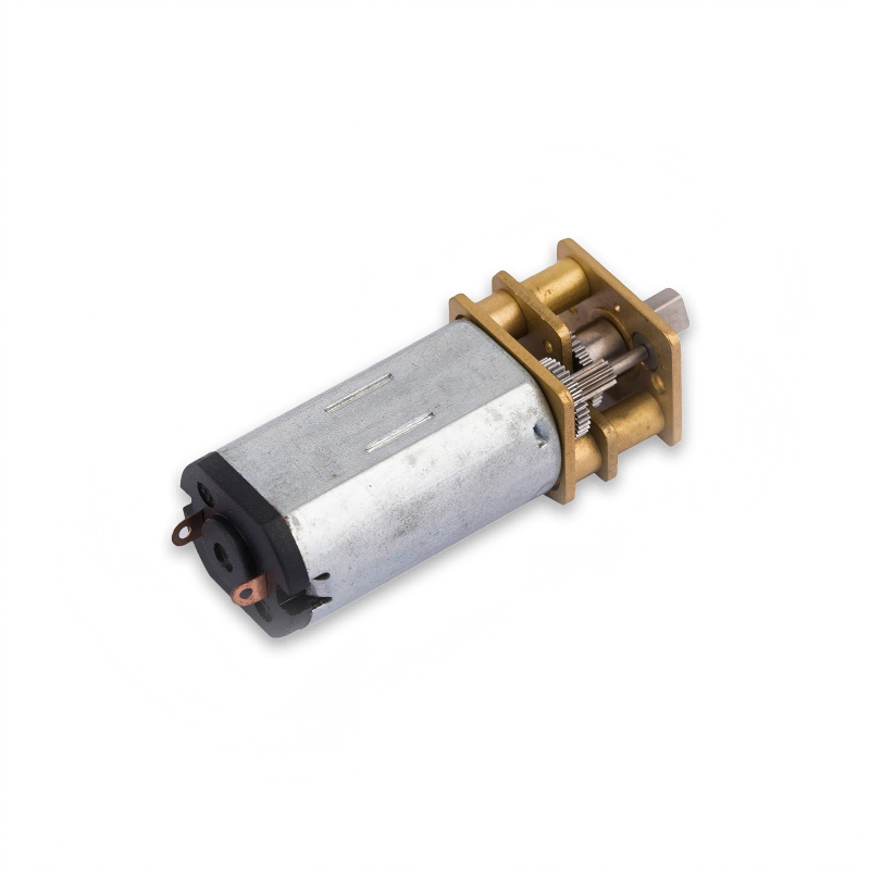
A spur gearbox motor compares favorably by offering an incredibly simple, highly efficient, and cost-effective drive solution for lower-torque, budget-sensitive applications. Spur gears feature straight teeth cut parallel to the axis of rotation, which makes them very straightforward to manufacture and assemble. Because there is minimal axial sliding friction between the meshing teeth, these gearboxes exhibit excellent mechanical efficiency at lower ratios. If your project does not demand extreme torque density or low backlash, spur gear assemblies provide the best possible return on investment.
Is mechanical efficiency really higher?
At low speed reduction ratios, a spur gear setup often outperforms a planetary or worm gearbox in pure efficiency terms because it experiences fewer gear-meshing friction points. You can expect up to 95% efficiency per gear stage, ensuring that very little energy is wasted as heat. The truth is: this efficiency drops as you stack multiple stages to achieve higher reduction ratios.
- Fewer internal moving parts translate to less rotational drag.
- Low heat generation makes these motors ideal for sealed, battery-operated devices.
- Straightforward design simplifies maintenance and lubricant replenishment.
Why consider noise and backlash limits?
Because the teeth engage along a single contact line all at once, spur gears tend to generate more operational noise than helical or planetary designs. Additionally, the inherent clearance required for smooth rotation results in slightly larger backlash values. Think about it: if you are building an office projector or a silent medical device, a loud hum could ruin the user experience. You must weigh the lower cost of spur gears against these acoustics and precision limits.
Key Takeaway: Spur gearboxes offer maximum efficiency and affordability for simple, straight-line, low-to-moderate torque applications.
| Characteristic | Spur Gearbox Profile | Application Impact | |
|---|---|---|---|
| Manufacturing Cost | Very Low / Economical | Keeps your overall bill of materials low | |
| Per-Stage Efficiency | Excellent (~95%) | Maximizes battery runtimes in mobile tools | |
| Noise Level | Moderate to High | Best suited for industrial or isolated housings |
Weigh these spur gear trade-offs to determine if you can achieve substantial cost savings without compromising essential performance.
Why Integrate an Encoder Gearbox Motor?
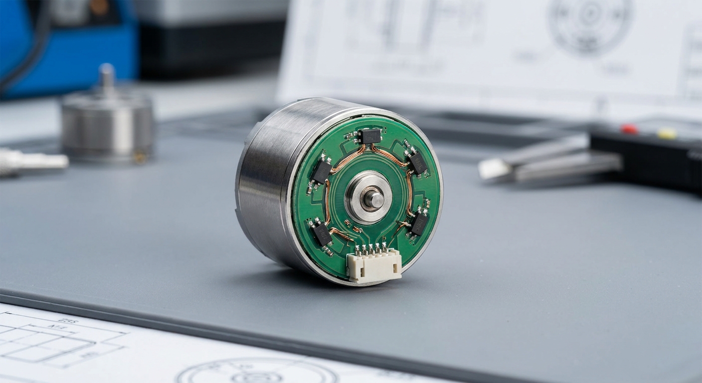
You should integrate an encoder with your brushless gearbox motor because it provides real-time rotational feedback, allowing your controller to monitor speed, position, and direction with extreme accuracy. Without feedback, your control system operates blindly, unable to adjust for unexpected torque resistance or speed fluctuations. Placing the encoder directly onto the motor shaft before the gearhead captures high-resolution data that is multiplied by the gear ratio. This integration gives you incredibly fine-grained mechanical resolution at the output shaft, enabling complex motion control profiles.
How does feedback loop control work?
The encoder constantly sends pulses to your drive controller, letting it compare the actual output position with the commanded target position. If the system detects a discrepancy due to a sudden external resistance, the controller immediately spikes the current to maintain speed. Here is the thing: closed-loop feedback prevents motor stalls and eliminates positioning errors entirely.
- Magnetic Hall-effect sensors offer durable, contactless operation.
- Optical encoders provide higher resolution for ultra-precise micro-movements.
- Quadrature outputs allow the controller to detect shaft rotation direction.
Does encoder placement matter?
Mounting the encoder on the motor shaft allows you to capture raw high-speed rotation before any gear backlash can distort the signal. This ensures that the motor’s electronic commutation remains perfectly synced and efficient under load. But wait, there’s more: you can also place a secondary encoder on the output shaft to measure actual mechanical output directly. This dual-encoder setup guarantees absolute accuracy by measuring and compensating for any gear wear.
Key Takeaway: Integrating an encoder transforms your gearbox motor into a smart closed-loop actuator capable of precise positioning.
| Encoder Type | Resolution Level | Environmental Resistance | Best Application | |
|---|---|---|---|---|
| Magnetic (Hall) | Moderate | Excellent (Resists dust & moisture) | Outdoor robotics, heavy industrial | |
| Optical | Extremely High | Sensitive to contamination | Laboratory automation, silicon wafer handling |
Refer to this encoder selection matrix to choose the ideal sensor technology for your operational environment.
Does a Brushless Gearbox Motor Save Costs?
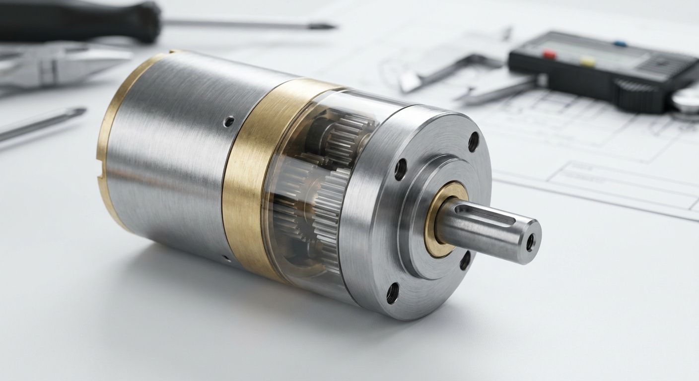
Yes, a brushless gearbox motor saves substantial costs over the lifespan of your equipment by drastically reducing maintenance requirements, improving energy efficiency, and expanding operating longevity. While a brushless system has a slightly higher upfront price than a brushed equivalent, it eliminates wearing parts like carbon brushes. Brushes degrade over time, leading to electrical sparking, carbon buildup, and eventually complete motor failure. By choosing a brushless solution, you eliminate routine maintenance downtime and avoid costly emergency equipment repairs.
How is lifetime reliability improved?
Without brushes to wear down, the overall lifespan of the motor is limited only by its internal ball bearings and gear tooth wear. This means a brushless system can easily run for tens of thousands of hours without requiring any manual intervention. Let’s face it: replacing a buried motor in a complex assembly line can cost thousands of dollars in lost production time.
- Contactless commutation eliminates friction and electric arcing hazards.
- Sealed brushless designs protect internal components from dust.
- Lower operating temperatures extend the lifespan of internal lubricants.
What are the energy efficiency gains?
Brushless motors convert a much higher percentage of electrical energy into mechanical power compared to traditional brushed motors. When you run automated machinery continuously, this improved efficiency can result in significant electricity cost savings. Think about it: scaling down your power supply and cabling requirements because of lower current draws can save you substantial upfront cash. It makes your entire electrical distribution system cheaper and safer to build.
Key Takeaway: Brushless designs yield major long-term savings by eliminating brush maintenance and maximizing power-use efficiency.
| Cost Component | Brushed Gearbox Motor | Brushless Gearbox Motor | |
|---|---|---|---|
| Initial Purchase Price | Low | Moderate to Premium | |
| Maintenance & Downtime | High (Periodic brush replacement) | Virtually Zero | |
| Operational Lifespan | ~1,500 – 3,000 Hours | Up to 20,000+ Hours |
Review this life-cycle cost breakdown to justify the long-term economic advantages of choosing brushless motor configurations.
Where Fits a Flat Gearbox Motor Design?
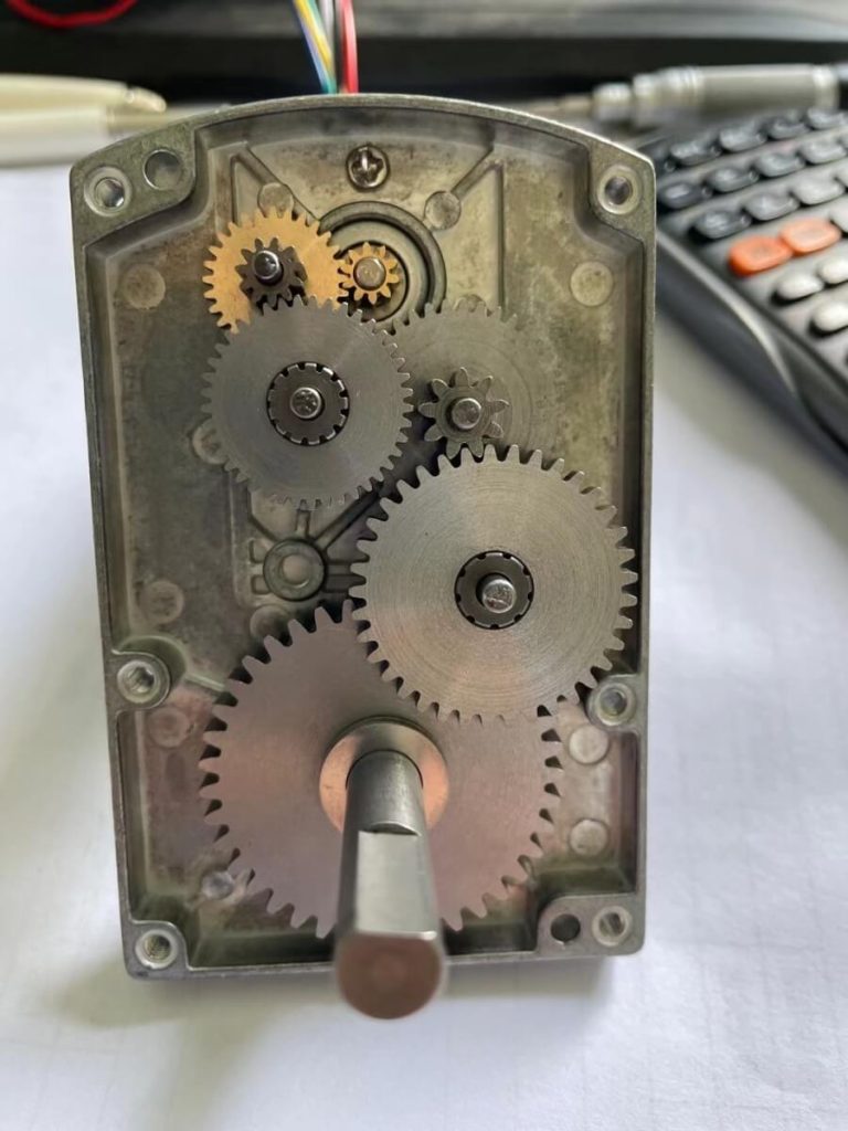
A flat gearbox motor design fits perfectly in applications with severe axial depth constraints, where standard cylindrical layouts simply cannot fit between structural plates or inside thin casing walls. By arranging the internal gearing in a flat plane, similar to a multi-stage spur gearbox motor , designers can dramatically compress the total length of the drive package. This slim profile is incredibly popular in thin medical drug-delivery pumps, handheld laboratory equipment, and automated window blinds. Choosing this form factor ensures that your mechanism remains incredibly sleek without sacrificing necessary driving force.
How is the flat profile achieved?
Engineers achieve this ultra-slim design by placing the motor and the gear stages side-by-side in parallel planes, rather than stacking them end-to-end. This horizontal gear arrangement shortens the length of the system but slightly increases its width. The truth is: this dimensional tradeoff is highly advantageous for flat wall-mounted enclosures.
- Parallel-shaft layouts keep the overall drive thickness minimal.
- High-grade composite or metal housings protect the wider gear face.
- Integrated face-mounting holes make securing the flat motor very easy.
Can you expect high torque?
You can still achieve high torque ratios because the flat design allows you to chain multiple gear stages efficiently across the flat casing plane. The rigid housing ensures that these flat-aligned gear axles do not bend under heavy load conditions. Here is the thing: a flat casing doesn’t mean weak performance if you use precision-hardened metal gears. It simply spreads the mechanical forces across a wider, shallower surface area.
Key Takeaway: Flat-profile gearboxes are ideal for compressing axial depth, making them perfect for sleek handheld devices and slim panel mountings.
| Dimension / Spec | Cylindrical Planetary Motor | Flat Parallel-Shaft Motor | |
|---|---|---|---|
| Axial Body Length | Long | Ultra-Short / Flat | |
| Enclosure Width | Narrow | Wide | |
| Primary Mounting Style | Face Flange Mount | Side Plate or Flat Face Mount |
Utilize this comparison to decide if your enclosure design requires a flat horizontal or a traditional inline drive profile.
How to Buy the Perfect Gearbox Motor?
To buy the perfect gearbox motor, you must carefully analyze your system’s peak torque, target operating speed, mounting space limits, and environmental conditions before consulting with a qualified manufacturer. Rushing into a purchase based on speed and voltage alone often results in premature gear failures or insufficient starting torque. Calculating your exact radial and axial shaft loads ensures that the gearhead bearings can withstand daily operations without breaking. Working with a dedicated B2B manufacturer ensures that you get a custom-tailored solution optimized for your specific industrial application.
What are the key specifications to gather?
Before speaking with a supplier, you should have a firm grasp of your electrical supply limits and mechanical performance targets. Gathering these parameters early prevents design delays and avoids costly ordering mistakes. Think about it: ordering a hundred motors only to discover the shaft diameter is wrong will derail your launch schedule.
- Maximum continuous torque required to move the load.
- Target speed range under full load conditions.
- Available physical volume and weight constraints.
How do you evaluate environmental needs?
You must consider whether your motor will operate in dusty, damp, or extremely high-temperature environments. Standard motors will quickly fail if fine particles bypass the seals and degrade the internal gear teeth or encoder circuitry. Let’s face it: a motor running in a medical lab needs different sealing than one driving an outdoor solar tracker. Choosing the right ingress protection rating protects your machinery from premature field failure.
Key Takeaway: Precise parameter gathering and rigorous environmental assessment are vital to purchasing a durable, high-performance gearbox motor.
| Parameter Checklist | Critical Consideration | Target Value (Fill in) | |
|---|---|---|---|
| Working Torque | Continuous vs. Peak startup torque | [Insert Target Nm/Ncm] | |
| Ingress Protection (IP) | Dust, water, or oil splash resistance | [Insert IP54 / IP65 / IP67] | |
| Available Envelope | Maximum length, width, and shaft diameter | [Insert Dimensions in mm] |
Use this specification checklist to prepare all necessary mechanical data before requesting a quotation from our engineering team.
Summary & Structural Recommendation
Selecting the ideal torque reduction setup is the defining step in maximizing the efficiency, reliability, and precision of your industrial automated systems. Whether you struggle with severe spatial limitations, low-speed torque stalls, or high maintenance costs, our expert team is ready to engineer the perfect solution. We specialize in tailoring custom, high-precision planetary, worm, and spur motion systems designed to survive the harshest industrial conditions. Let us power your next breakthrough in smart automation— contact us today to collaborate with our engineering experts and bring your high-performance motion designs to life.
Frequently Asked Questions
Can I run a gearbox motor backward without damaging the internal gears?
Yes, most designs allow bi-directional rotation, provided you do not exceed the specified torque ratings during reversal. Reversing the motor simply changes the direction of the tooth engagement, though you must account for internal backlash during direction changes. However, certain high-ratio worm gear setups are self-locking and cannot be backdriven from the output shaft, so always verify your specific gear geometry.
What is the best way to calculate the required torque for my design?
The best way is to measure the maximum friction and load inertia under worst-case operating conditions. You must calculate the starting torque required to accelerate the load from a standstill, as this is usually significantly higher than the continuous running torque. Multiplying this value by a safety factor of 1.5 to 2.0 ensures that your system can handle unexpected mechanical resistance without stalling.
How do I know if my application requires a brushless motor over a brushed one?
You require a brushless motor if your system demands continuous duty, extremely long operating lifespans, or high-speed precision. Brushed motors are excellent for low-cost, intermittent-use products, but they wear down quickly under heavy, continuous industrial schedules. Brushless systems eliminate brush wear, run cooler, and interface seamlessly with high-resolution encoders for precise closed-loop control.
Can a planetary gearbox handle high shock loads?
Yes, planetary systems are exceptionally well-suited for handling high shock loads due to their inherent multi-tooth load-sharing design. Because the torque is distributed among several planetary gears, the physical stress on any single tooth is minimized, preventing mechanical chipping or deformation. For extreme shock applications, selecting metal gears over plastic ones is highly recommended to ensure structural integrity.
How often does a miniature gearbox motor require lubrication?
Most high-quality miniature gearbox motors are lubricated for life at the factory and do not require any user maintenance. They are filled with specialized synthetic grease or oil designed to withstand the motor’s rated temperature range and operational lifespan. If your equipment operates under extreme temperatures or vacuum conditions, you must specify this during purchase so the manufacturer can apply a compatible specialty lubricant.