
DC gear motor are integrated electromechanical devices that combine a direct current electric motor with a mechanical gearbox, working by utilizing electromagnetic forces to rotate an internal rotor and then multiplying that force through reduction gears to deliver high torque at lower speeds. As a design engineer working on modern robotic joints or automotive actuation systems, you frequently face the challenge of generating high mechanical torque within extremely confined physical envelopes. Standard electric motors spin far too fast and lack the raw turning power needed to move heavy physical loads directly.
If you attempt to solve this by pairing mismatched, bulky external gearboxes with standard high-speed motors, you run into severe efficiency losses, alignment issues, and backlash. This improper matching can ruin your system’s battery life, generate excessive heat, and ultimately lead to early mechanical failure. The ultimate solution to this engineering bottleneck is the integrated dc gear motor , which combines both power and precision into a single compact housing.
What Is a DC Gear Motor?
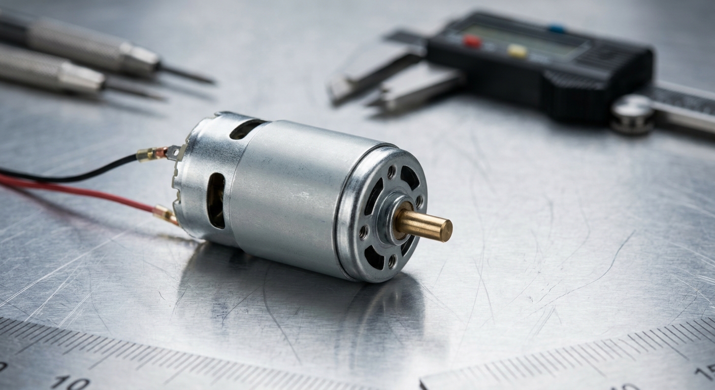
A dc gear motor is a unified electromechanical power source designed to provide precisely controlled rotational speed and torque. By permanently pairing a DC electric motor with an engineered gearhead, this system simplifies power transmission in small-scale systems. You get a reliable, plug-and-play actuator that eliminates the complexity of designing separate mechanical drivetrains from scratch.
This integrated design is essential for modern automated applications where space is at a premium. By matching the motor’s high-speed characteristics with the gearbox’s reduction ratio, engineers achieve optimal system efficiency and performance.
What Defines the Core Electromechanical Unit?
At its core, this electromechanical unit functions by transmitting raw electrical energy into a mechanical gearbox that alters speed and torque. When you supply direct current, the motor’s rotor spins rapidly, driving an input pinion gear.
This input gear immediately engages the teeth of the gearbox stages, converting high-speed rotation into high-torque output.
- Pinion Gear: Transmits the high-speed input from the motor shaft.
- Reduction Gears: Multiply torque while reducing speed according to the gear ratio.
- Output Shaft: Delivers the final mechanical power to your driven application.
The Evolutionary Journey of Micro Drives
Historically, engineers relied on large belt-and-pulley or chain-and-sprocket systems to achieve high torque in industrial machinery. These traditional setups were prone to slippage, required frequent maintenance, and occupied far too much space. Today, the transition to integrated micro drives has revolutionized space-constrained engineering designs.
You can now deploy micro gearheads that fit in the palm of your hand yet deliver incredible force. This shift allows you to create lighter, smarter, and more reliable products without sacrificing mechanical capability.
Key Takeaway: Integrated micro drives replace complex external gear assemblies, saving physical space and maximizing the reliability of your mechanical designs.
| Metric | Traditional Belts/Pulleys | Modern Micro Gearhead | |
|---|---|---|---|
| Power Density | Low | Extremely High | |
| Maintenance Need | High | Zero (Sealed for Life) | |
| System Backlash | Variable | Highly Controlled |
The combination of dense epicyclic gears and compact brushless or brushed motors ensures your designs achieve the highest power efficiency possible.
How Is a DC Gear Motor Built?
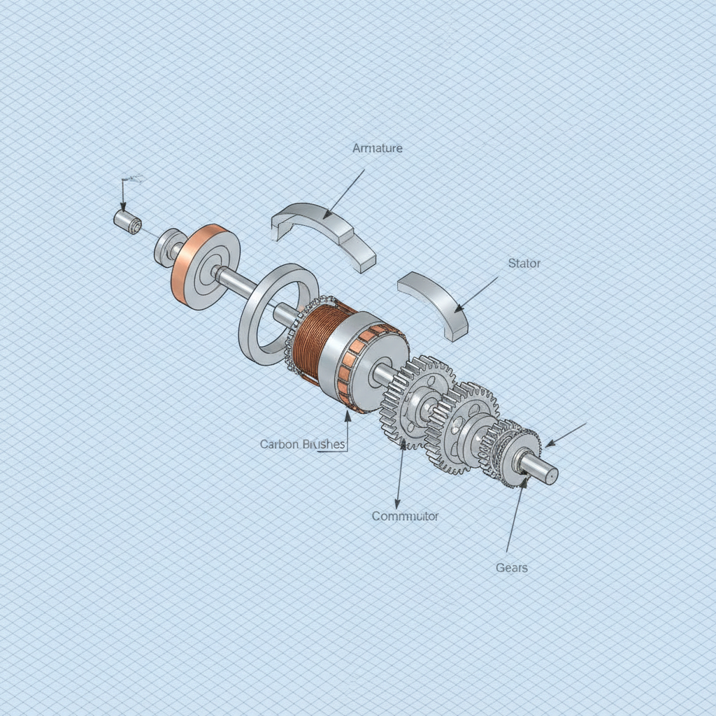
A DC gear motor is built by structurally mounting an electric motor block directly to a matching mechanical gearbox housing. This alignment ensures that the rotor’s output shaft acts as the direct input to the gears. By housing these components together, the system protects delicate internal gears and electrical windings from environmental dust.
Every structural element is selected to balance weight, durability, and cost. Understanding this mechanical anatomy allows you to make informed decisions for your specific automation projects.
What Lies Inside the Direct Current Motor Core?
Inside the motor section, you will find a stator, a wire-wound rotor, and a mechanical commutation system. The stator generates a fixed magnetic field using permanent magnets, while the rotor acts as an electromagnet when energized.
Here is the deal: The commutator and carbon brushes continuously swap the direction of the electrical current as the rotor spins.
- Stator Magnets: Provide the permanent magnetic flux field.
- Armature Windings: Conduct current to generate electromagnetic forces.
- Brushes and Commutator: Direct electrical current to the correct rotor coils.
Understanding the Gearhead Integration
The gearbox section acts as a mechanical torque multiplier by transferring power through a series of interlocking teeth. A precision pinion gear is pressed directly onto the motor’s spindle to prevent any rotational slippage. This pinion drives the larger gears, which sequentially reduce speed while raising torque.
You must ensure that the alignment between these mating faces is absolutely perfect during assembly. Any minor misalignment can increase friction, noise, and speed losses in your final application.
Key Takeaway: Perfect structural alignment between the motor spindle and the first-stage gears dictates the ultimate operating lifespan of your motion system.
| Component Group | Material Composition | Primary Engineering Role | |
|---|---|---|---|
| Motor Core | Plated Steel & Copper Wires | Converts electrical energy to mechanical rotation | |
| Gear Train | Sintered Steel / Plastics | Translates high rotational speed into usable torque | |
| Shaft Assembly | Hardened Carbon Steel | Transmits mechanical power to external physical loads |
Always analyze the material specs of your gear motor to guarantee it can withstand the physical forces of your specific working environment.
How Does a DC Gear Motor Work?
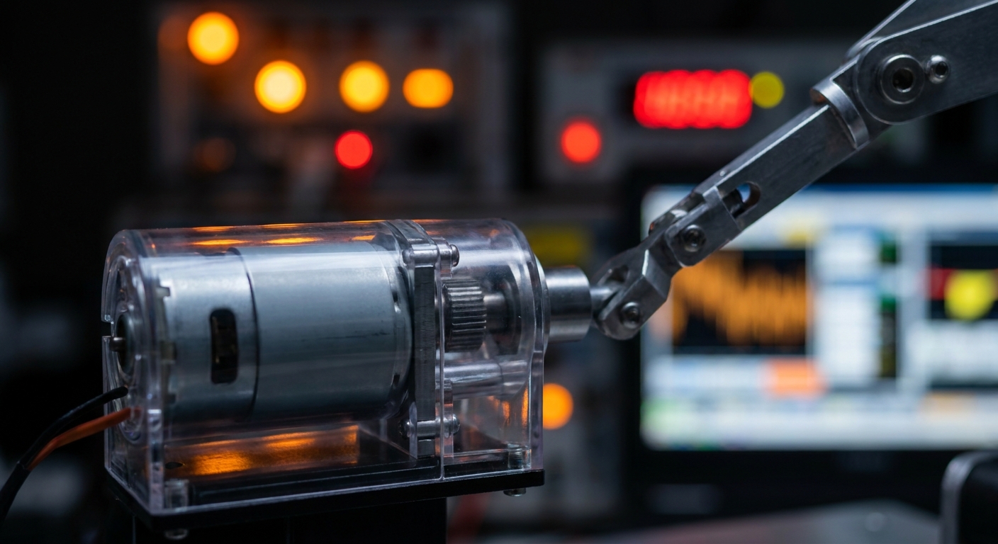
A dc gear motor works by converting direct current electrical energy into mechanical rotation, which is then passed through a reduction gear train to amplify torque. The electromagnetic interaction inside the motor generates high-speed rotational force. This high-speed rotation is instantly modified by the gear ratios to provide the slower, stronger output you need.
By controlling the input voltage, you can easily govern the output speed of the entire assembly. This elegant simplicity makes these motors highly popular for precise motion control applications.
Converting Electricity into Rotation
The conversion process relies on the Lorentz Force principle, where a current-carrying conductor in a magnetic field experiences a physical force. When you apply DC power, the magnetic fields of the stator and rotor oppose each other, forcing the rotor to spin.
This force is continuous, providing smooth, reliable rotational power as long as voltage is applied.
- Voltage Input: Controls the initial speed of the electromagnetic rotor.
- Magnetic Flux: Determines the strength of the rotational force.
- Commutation Switching: Maintains constant one-directional rotation.
How Do Gearing Ratios Multiply Output Torque?
Gearing ratios multiply torque by trading rotational speed for mechanical advantage through interlocking gear teeth. If your motor spins at 3,000 RPM and you attach a 100:1 reduction gearbox, the output shaft will spin at a controlled 30 RPM. This trade-off multiplies the torque by nearly one hundred times, minus minor efficiency losses.
You can easily calculate the exact output speed and torque by evaluating your gearbox’s reduction ratio. This mathematical certainty makes system integration highly predictable.
Key Takeaway: Gearing ratios allow you to exchange excess rotational speed for extreme mechanical turning force, solving low-speed high-torque problems.
| Reduction Ratio | Speed Reduction | Torque Multiplication | Efficiency Impact | |
|---|---|---|---|---|
| Low (e.g., 5:1) | Minimal | Low | Very Low (95% efficient) | |
| High (e.g., 100:1) | Significant | High | Moderate (75% efficient) |
Choosing the correct reduction ratio ensures your motor operating speeds stay within their peak performance and thermal efficiency windows.
Which Gearbox Fits a DC Gear Motor?
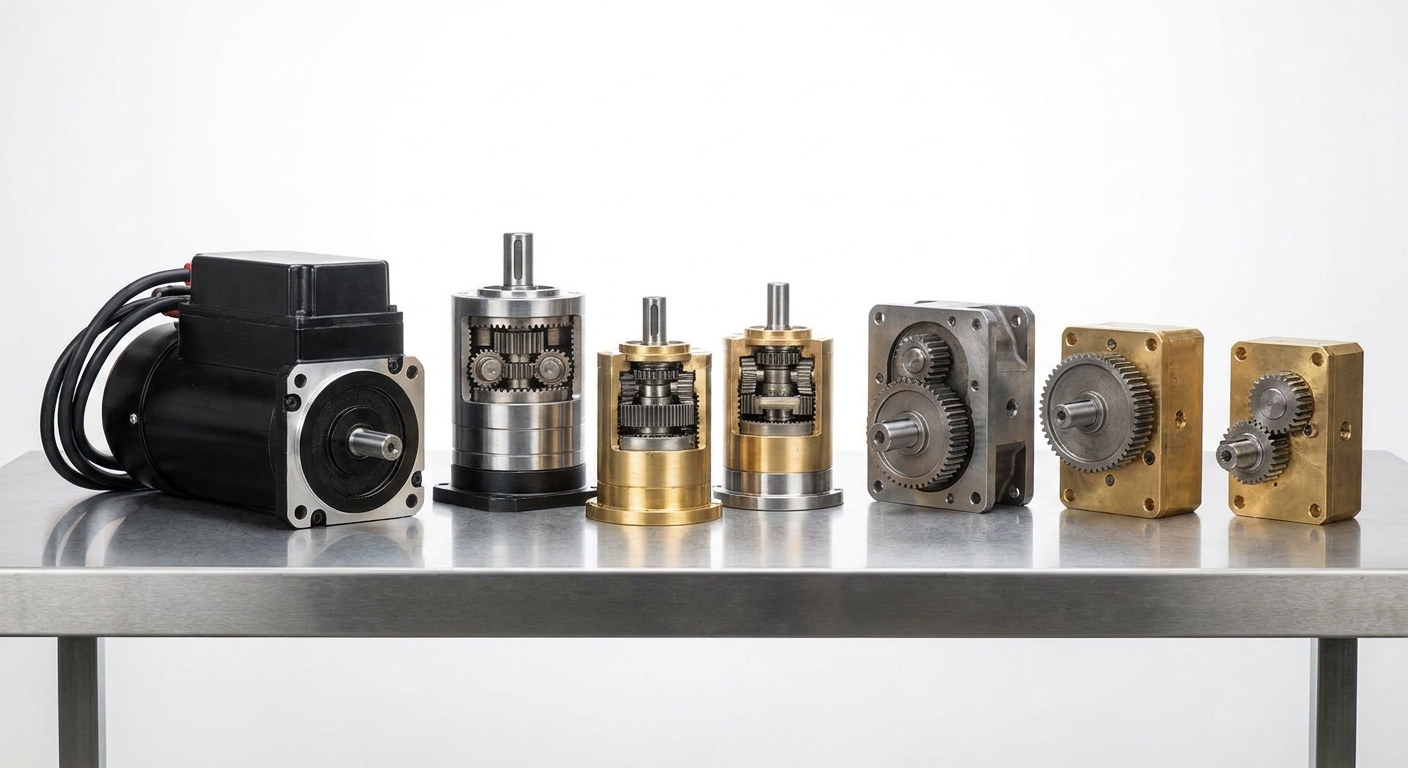
Choosing which gearbox fits a DC gear motor depends on your application’s physical space, torque demands, and axial load limits. Common configurations include planetary, spur, and right-angle worm gear systems. Each design offers unique mechanical advantages to optimize your machine’s performance.
By matching the correct gearbox configuration to your motor, you can ensure smooth energy transmission and minimize operational noise. Let’s break down the primary choices available to you.
Why Choose Planetary Systems for Power Density?
Planetary gearboxes offer the highest torque-to-volume ratio by sharing the mechanical load across multiple planet gears simultaneously. This load-sharing capability prevents tooth wear and keeps the entire drive inline with the motor shaft.
They provide exceptional efficiency and minimal backlash, making them perfect for high-precision applications like robotics.
- Sun Gear: The central input gear connected directly to the motor spindle.
- Planet Gears: Multiple gears that rotate around the sun to distribute mechanical loads.
- Outer Ring Gear: The static outer teeth that guide the planets’ paths.
Spur and Right-Angle Gear Arrangements
Spur gearboxes are highly cost-effective and simple, making them perfect for lower-torque, budget-sensitive applications. If you face extreme space constraints along the motor’s axial length, a right-angle worm gearbox is your best option. Worm drives also offer natural self-locking capabilities to keep loads in place when powered down.
You must carefully weigh these spatial constraints against your torque demands to select the right fit. This geometric choice is critical to avoiding installation headaches later on.
Key Takeaway: Selecting the correct gearbox geometry saves valuable system space and prevents mechanical failure under heavy radial loads.
| Gearbox Configuration | Power Density | Noise Level | Self-Locking Ability | |
|---|---|---|---|---|
| Planetary | Extremely High | Moderate | No | |
| Spur | Moderate | Moderate | No | |
| Right-Angle Worm | High | Very Low | Yes |
Prioritize planetary gearboxes when your application requires maximum torque output within a highly compact inline coaxial installation profile.
Why Use a PMDC-Based DC Gear Motor?
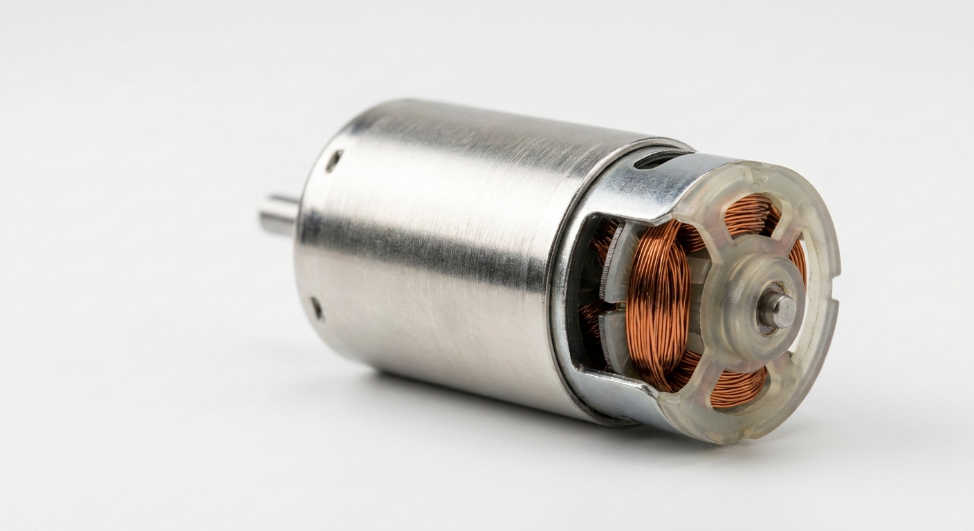
You should use a PMDC-based dc gear motor because permanent magnet designs provide high starting torque, excellent thermal efficiency, and a highly linear speed-to-torque relationship. Unlike wound-field motors, permanent magnet motors do not waste electrical power on energizing field coils. This makes them highly efficient and lightweight for battery-powered systems.
These characteristics make PMDC configurations highly popular in modern consumer electronics, medical pumps, and smart home systems. Let’s explore how these magnets improve your system’s performance.
The Mechanics of Permanent Magnets
Permanent magnets are mounted inside the motor stator to provide a constant magnetic flux without drawing current. This design reduces internal heat generation, allowing the motor to run cooler during continuous duty cycles.
Because there are no stator windings to overheat, you get a much safer and more reliable drive system.
- Neodymium Magnets: Deliver maximum flux density for extreme torque outputs.
- Ferrite Magnets: Provide a highly cost-effective solution for standard applications.
- Magnetic Stability: Maintains steady torque output across a wide temperature range.
Optimizing Small-Scale Performance
PMDC motors exhibit a linear performance curve, meaning their speed decreases proportionally as the torque load increases. This linear predictability makes programming speed controllers and feedback loops incredibly straightforward. You can easily maintain consistent control over your motorized devices under varying physical loads.
You must remember that this ease of control is a major reason why designers choose PMDC platforms for high-performance micro applications. It saves engineering hours and reduces control system complexity.
Key Takeaway: PMDC platforms maximize starting torque and thermal efficiency, simplifying controller design in small-scale systems.
| Magnet Type | Flux Density | Temperature Limit | Cost Impact | |
|---|---|---|---|---|
| Neodymium (NdFeB) | Extremely High | Up to 150°C | Premium | |
| Ferrite (Ceramic) | Moderate | Up to 250°C | Cost-Effective |
Select neodymium magnets for high-power robotic applications, and opt for ferrite when keeping production costs low is your primary goal.
Where Do We Use a DC Gear Motor?
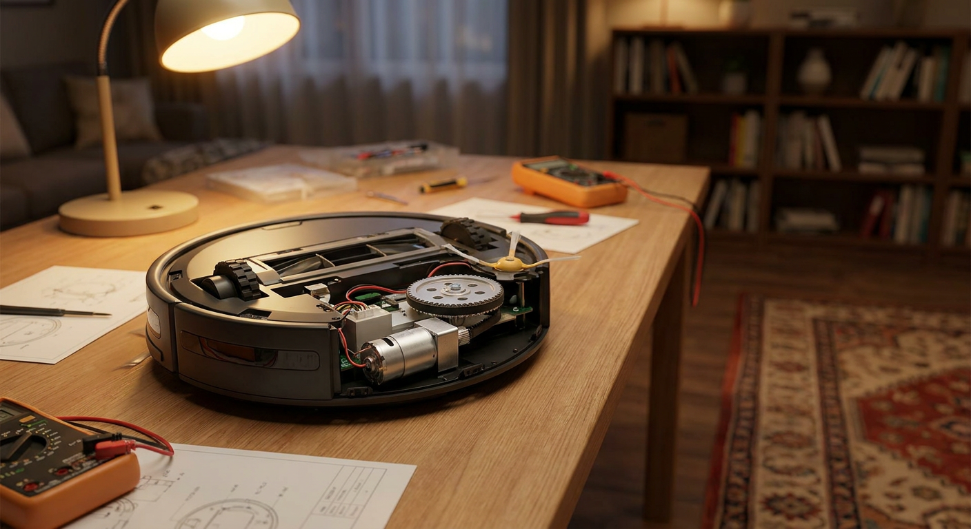
We use a DC gear motor across a vast range of applications including smart home appliances, automotive safety systems, medical devices, and industrial automation. Any system requiring compact, quiet, and highly reliable rotary force relies on these electromechanical units. Their high torque-to-weight ratio makes them irreplaceable in modern automated devices.
From the lock on your front door to the wipers on your vehicle, these quiet workhorses operate silently in the background. Let’s look closer at where they are deployed most effectively.
Driving Smart Home and Consumer Devices
Smart homes rely heavily on micro gear motors to operate motorized blinds, smart door locks, automated security cameras, and robotic vacuums. These applications require high torque to move deadbolts or wheels, but they must fit inside highly aesthetic, compact consumer housings.
Here is the deal: Without these miniature gearheads, your smart devices would be twice as bulky and far noisier.
- Smart Locks: Require right-angle or planetary systems to actuate deadbolts.
- Robotic Vacuums: Depend on high-reduction gearmotors to drive drive wheels.
- Motorized Curtains: Use quiet inline planetary drives for smooth pull cycles.
Precision Motion in Automotive Systems
In the automotive industry, manufacturers use high-reliability gearheads for electronic parking brakes, side-mirror adjusters, active headrests, and power tailgates. These components face extreme outdoor temperature swings and must operate flawlessly for years without maintenance.
You can rely on specialized lubricants and sealed gearcases to survive these harsh environmental conditions. This durability ensures passenger safety and vehicle luxury systems run smoothly.
Key Takeaway: Modern consumer and automotive systems depend on compact gear motors to deliver high actuation forces in tight spaces.
| Application Area | Key Operational Requirement | Best Gearbox Type | |
|---|---|---|---|
| Smart Lock Actuators | High torque and self-locking | Worm or Compact Planetary | |
| Automotive Mirrors | Ultra-compact, low weight | Miniature Spur Gearhead | |
| Medical Pump Systems | Low noise and precise speed | High-Ratio Planetary |
Choose high-grade planetary gear motors for any high-vibration automotive environment to ensure your product survives lifetime testing.
What Benefits Does a DC Gear Motor Offer?
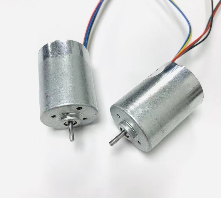
A dc gear motor offers exceptional benefits such as high starting torque, highly linear speed control, exceptional power density, and incredibly simple electronic drive requirements. These systems allow you to control massive physical loads using basic electronic circuits. This simplicity reduces your overall system cost and increases mechanical reliability over long operating periods.
Whether you need fine-grained control over a robotic arm or rugged power for an industrial valve, these motors perform exceptionally well. Let’s analyze these core benefits in detail.
Can You Expect Superior Starting Torque?
Yes, DC motors naturally generate their maximum torque at zero RPM, providing the high starting force needed to move heavy stationary loads. When paired with a gearbox, this starting torque is multiplied even further.
The best part? You do not need expensive variable frequency drives to control this starting current or torque.
- Maximum Torque at Stall: Instantly breaks stationary friction in mechanical loads.
- Linear Voltage Control: Adjusting the voltage provides smooth, linear speed adjustment.
- Simple Reversibility: Swapping electrical polarity changes rotation direction instantly.
Compact Footprint with High Performance
By utilizing a high-speed micro motor paired with a reduction gearbox, you can achieve the same power output as a direct-drive motor several times its size. This drastic reduction in weight and volume allows you to design sleeker, more ergonomic products.
You can pack high-performance actuation into tiny spaces that were previously impossible to motorize. This spatial efficiency is a massive competitive advantage for modern physical hardware designers.
Key Takeaway: Pairing high-speed motors with gearheads delivers high power density, allowing you to minimize product size and weight.
| Feature / Benefit | DC Gear Motor Performance | AC Motor Alternative | |
|---|---|---|---|
| Starting Torque | Exceptional at zero speed | Moderate to Poor | |
| Control Simplicity | Low (simple PWM drive) | High (complex phase drives) | |
| Sizing Footprint | Very small and inline | Bulky and heavy |
By choosing a compact DC-driven gear motor, you can reduce both your physical build space and your bill-of-materials costs.
How Do You Select a DC Gear Motor?
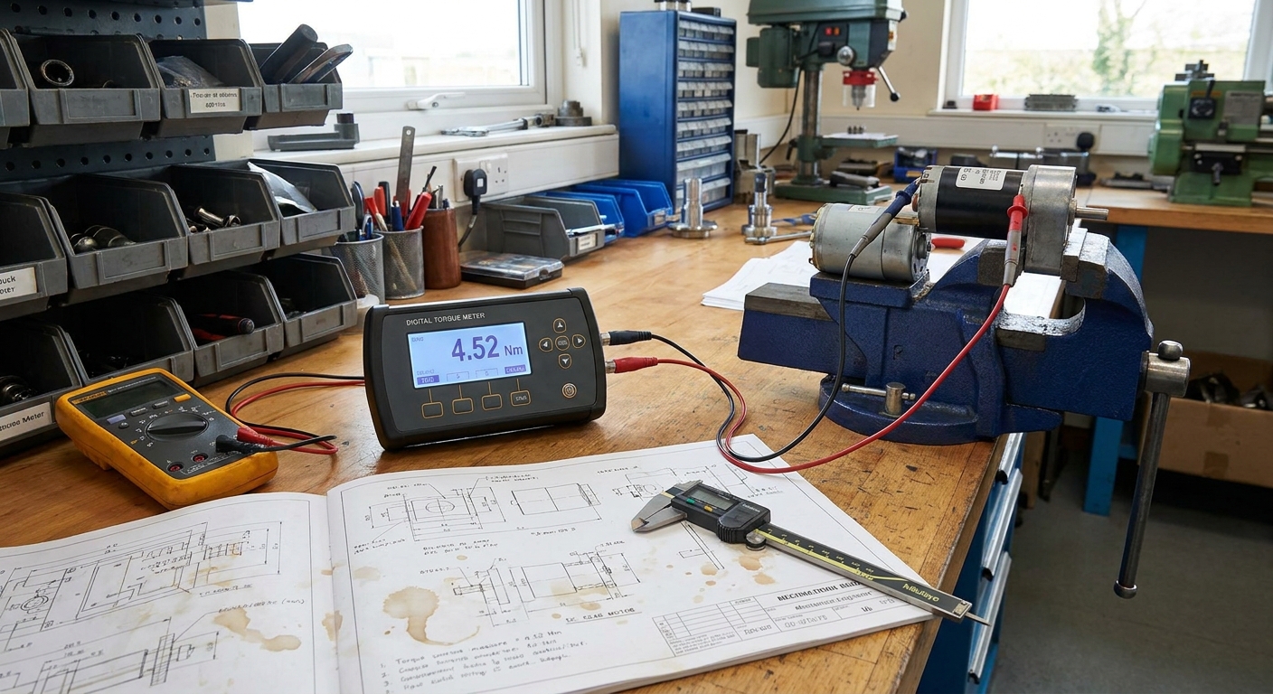
You select a DC gear motor by calculating your application’s load torque, determining your target operating speed, and evaluating your system’s duty cycle. Failing to properly calculate these parameters can lead to motor stalling, overheating, or early gear breakage. Taking the time to calculate these specs upfront guarantees a reliable, long-lasting mechanical design.
Let’s walk through the exact sizing steps you should take. This systematic approach ensures you choose the perfect model for your engineering project.
How Do You Calculate Target Speed and Torque?
To calculate target torque, you must measure the physical force needed to move your load and multiply it by the radius of your driving pulley or arm. Once you have this continuous torque value, you should add a 20% safety margin to account for environmental variables like cold weather or dust friction.
This safety factor ensures your motor has enough overhead to handle unexpected load spikes.
- Continuous Load Torque: The steady force required during normal operation.
- Peak Starting Torque: The initial torque spike needed to start motion.
- Operating Speed (RPM): The rotation speed your application requires.
Evaluating System Efficiency Metrics
Gearbox friction and mechanical losses will reduce the overall efficiency of your drive assembly. Multi-stage gearboxes have more meshing teeth, which increases friction and reduces the mechanical energy transmitted to the output shaft.
You must factor in these thermal and friction losses when calculating your power supply and battery capacity. This calculation prevents system voltage drops and power supply overloads during heavy load conditions.
Key Takeaway: Over-specifying a motor increases system costs, while under-specifying leads to premature overheating and field failures.
| Sizing Parameter | Engineering Unit | Failure Risk | |
|---|---|---|---|
| Continuous Torque | Newton-meters (Nm) | Motor stalls under heavy operating loads | |
| Rated Speed | Revolutions per Minute | Application runs too slow or fast | |
| Duty Cycle Percentage | percentage (%) | Motor overheats and melts coil insulation |
Always verify your torque and speed calculations on a dynamometer before locking in your final production motor specifications.
How Will You Integrate a DC Gear Motor?
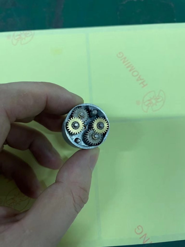
You will integrate a dc gear motor by aligning its mechanical mounting faces, coupling the output shaft securely, and implementing electrical current-limiting protection. Proper installation prevents radial shaft loads from bending your gearbox’s internal bearings. Taking these steps ensures your physical assembly operates smoothly for its entire designed service life.
Let’s explore the best practices for mechanical mounting and custom integration. These practical guidelines will prevent common installation failures in your hardware.
Future-Proofing Your Mechanical Systems
To future-proof your system, you should always use flexible shaft couplings to absorb any tiny parallel or angular misalignments. Direct rigid coupling can transfer bending forces back into your gearbox, causing rapid tooth wear and noise.
Here is the deal: Adding a simple inline fuse or active current-limiting sensor protects your windings from burning out during a mechanical stall.
- Flexible Couplings: Absorb axial vibrations and minor mounting misalignments.
- Current Limiters: Cut electrical power during sudden mechanical lockups.
- Sealed Housings: Keep high-viscosity gearbox lubricants from escaping.
When Should You Choose Custom Gear Motors?
You should choose custom gear motors when off-the-shelf options cannot meet your exact torque, shaft geometry, or noise requirements. Professional manufacturers can customize shaft lengths, gear ratios, lubrication formulas, and electrical connectors to match your product perfectly.
By cooperating with an experienced engineering team, you can quickly optimize your motor’s performance for high-volume production. This engineering partnership saves you time and guarantees a high-quality product.
Key Takeaway: Early planning for shaft alignment and electrical safety prevents field failures and significantly reduces your long-term maintenance costs.
| Integration Aspect | Best Engineering Practice | Primary Preventative Benefit | |
|---|---|---|---|
| Shaft Connection | Deploy flexible elastomer couplings | Eliminates radial bearing stress | |
| Electrical Line | Integrate current-limiting circuitry | Prevents motor winding burnout | |
| Mechanical Mount | Use rigid precision-machined brackets | Ensures perfect gear face alignment |
Partnering with a dedicated manufacturer early in your design cycle allows you to seamlessly integrate customized drive solutions.
What FAQs Resolve DC Gear Motor Doubts?
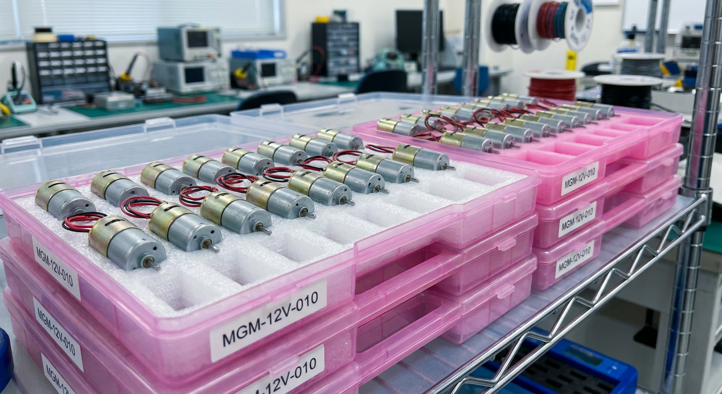
The following FAQs resolve common DC gear motor doubts regarding setup, polarity control, speed modulation, and operational troubleshooting. Understanding these technical nuances helps you maintain optimal performance and prevent premature component failure in the field. Let’s address the most common practical questions asked by designers.
By mastering these basic troubleshooting steps, you will save valuable development time. These answers provide clear, actionable advice for your physical motion designs.
Reader Queries on Setup and Maintenance
The practical answers provided below will help you avoid common integration mistakes and optimize your drive setup. Let’s dive straight into these frequently asked questions to resolve your technical doubts.
- Polarity Swapping: Instantly changes the rotation direction of your drive shaft.
- PWM Control: The industry standard for high-efficiency speed management.
- Lubrication Care: Prevents gear wear and reduces operational noise over time.
Can I run a DC gear motor in reverse?Yes, reversing the polarity of the applied DC voltage instantly changes the direction of the current through the rotor, reversing the rotation of the motor and gearbox. For brushless DC configurations, direction is managed through the controller’s phase switching sequence.
What’s the best way to control the speed of a DC gear motor?Pulse Width Modulation (PWM) is the industry-standard method for speed control. By pulsing the DC voltage at high frequencies, you can adjust the average voltage delivered to the motor, enabling smooth speed control while maintaining higher torque than direct voltage-dropping methods.
How long do the carbon brushes in a brushed DC gear motor typically last?Brush life ranges from 1,500 to 5,000 operational hours depending on operating speeds, electrical currents, and environmental dust. To extend system life in sealed or hard-to-access applications, consider brushless DC (BLDC) motor alternatives.
Can I use standard lubricants inside the gearbox housing?No, standard industrial oils can leak out or attack synthetic gears. Always use synthetic, high-viscosity greases designed for closed gears. These are formulated to resist shear and stay in the gear mesh across a wide temperature range.
What causes a DC gear motor to draw excessive current and overheat?This issue is typically caused by mechanical overload or binding in the drivetrain. When the gearbox output shaft faces loads beyond its rated capacity, the motor slows down, back-EMF drops, and winding current increases, which generates rapid heat buildup.
Key Takeaway: Understanding polarity, PWM control, and proper synthetic lubrication ensures your gear motors operate reliably and maintain peak performance throughout their lifecycle.
Conclusion
Designing the perfect motion system requires balancing torque, speed, and size constraints. Whether you are developing smart home devices, automotive safety systems, or precision medical pumps, choosing the right electromechanical drive is critical to your project’s success. An integrated, high-efficiency motor and gearhead configuration solves your low-speed, high-torque challenges without sacrificing valuable physical space.
At iSky Motor, we specialize in delivering high-precision miniature DC geared motors, planetary/spur gearbox systems, and custom drive engineering. Our technical experts can customize gear ratios, shafts, lubricants, and mounting brackets to match your exact application specifications. If you are ready to elevate your product’s performance with a high-density, reliable drive system, contact us today to discuss your project requirements with our engineering team. We are committed to powering global innovation with precision motion solutions that move the world forward.