
A DC planetary gear motor is the ultimate power solution because it delivers unmatched torque density, high efficiency, and exceptional precision within an incredibly compact spatial footprint. Many engineering teams struggle with standard motors that stall under high loads or fail to fit into modern, tightly-packed product enclosures. This mismatch forces you to choose between bulky systems that ruin your design aesthetic or weak motors that burn out, causing costly field failures and customer frustration. By upgrading to a high-performance dc planetary gear motor , you gain access to an optimized gear arrangement that distributes load evenly, drastically extending system life while maximizing torque output.
How Does a DC Planetary Gear Motor Control Speed?
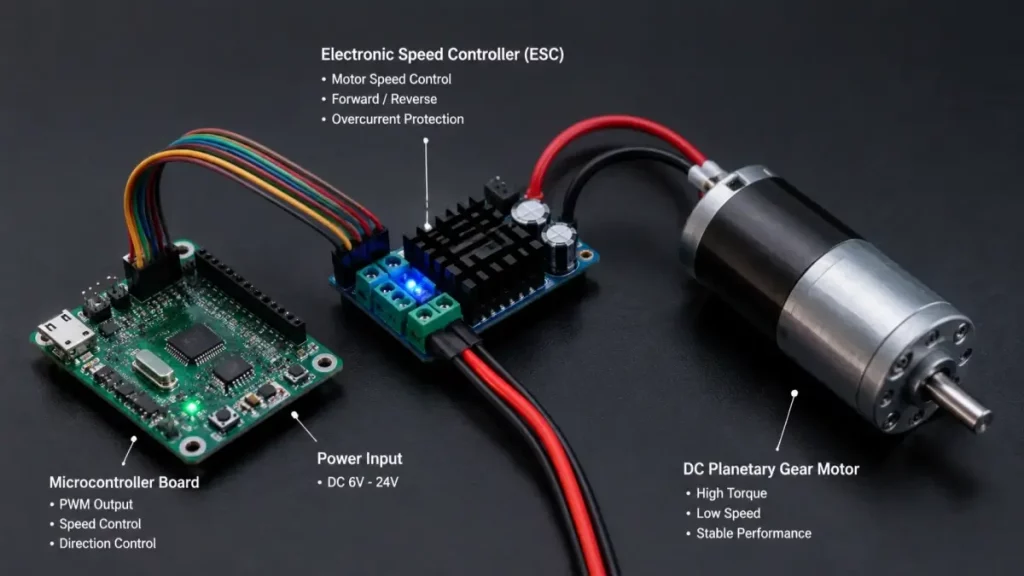
A DC planetary gear motor controls speed by combining electronic pulse-width modulation (PWM) from a controller with the mechanical reduction ratio of its gear stages. By adjusting the voltage input to the dc planetary gear motor , engineers can achieve highly linear speed variations that remain stable even under fluctuating load conditions.
Electronic Controller Integration
Microcontrollers and electronic speed controllers (ESCs) send precise electrical pulses to adjust the motor’s average voltage. Utilizing real-time feedback loops from integrated encoders allows the controller to make micro-adjustments in milliseconds.
Without high-speed switching feedback, keeping a steady rotational velocity under heavy loads is nearly impossible.
- PWM Duty Cycle: Alters current to regulate motor speed seamlessly.
- Encoder Feedback: Measures real-time shaft rotation to adjust controller outputs.
Mechanical Gear Reduction Stages
The gear ratio itself physically reduces high motor RPM down to a usable, high-torque output speed. Every additional planet stage multiplies the torque output while inversely stepping down the output velocity. This mechanical trade-off ensures that the motor operates within its optimal efficiency band.
Key Takeaway: Proper speed control requires a synergy between fine electronic PWM signals and robust mechanical gear reductions to prevent stalling.
| Control Type | Accuracy | Load Stability | Cost Impact | |
|---|---|---|---|---|
| Open-Loop PWM | Medium | Low | Low | |
| Closed-Loop Encoder | Very High | High | Medium | |
| Mechanical Gear Ratio | Absolute | Maximum | Structured |
Engineers should evaluate both duty cycle limits and mechanical backlashes when defining dynamic speed profiles.
Where is a DC Planetary Gear Motor Used Today?

A dc planetary gear motor is used across modern automation systems, medical robotics, smart home devices, and advanced defense equipment requiring high reliability. Whenever an application demands maximum torque delivery from a minimal physical volume, the dc planetary gear motor is the industry-standard choice.
Industrial Robotics and Logistics
Modern automated guided vehicles (AGVs) and warehouse sorting robots rely on these motors to carry heavy payloads through tight spaces. The compact concentric design allows drive systems to fit directly inside small wheel hubs.
If these motors fail for even an hour, entire fulfillment pipelines grind to an expensive halt.
- Robotic Arms: High-precision joint movements.
- AGV Drive Wheels: Constant heavy-duty tractive force.
Precision Medical Instruments
Surgical robots and fluid pumps require flawless, jitter-free rotation at extremely low speeds to protect patient safety. The concentric design of planetary gearheads provides the smooth, centered rotation needed for delicate operations. Additionally, their minimal backlash keeps instruments aligned perfectly with surgical coordinates.
Key Takeaway: High torque densities and unmatched positional accuracy make these motors indispensable in space-critical automation environments.
| Industry Sector | Primary Benefit | Required Lifespan | Typical Duty Cycle | |
|---|---|---|---|---|
| Robotics & AGVs | High Torque Density | Long | Continuous | |
| Medical Devices | Low Backlash & Noise | Medium | Intermittent | |
| Aerospace | Extreme Reliability | High | Critical |
Mapping the duty cycle of your target environment is critical to selecting the correct mechanical gear stage architecture.
Why Choose a DC Planetary Gear Motor for Efficiency?
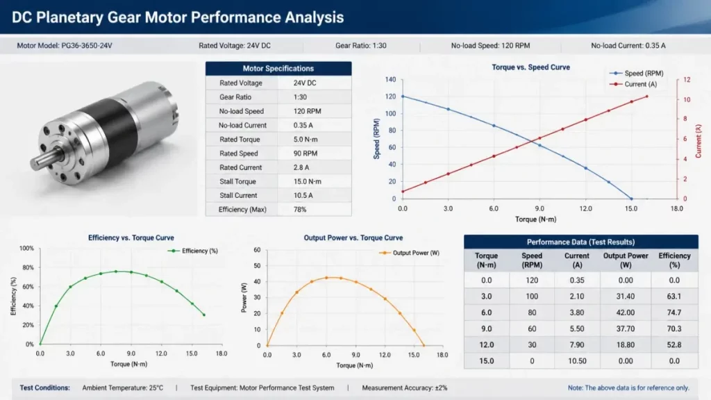
You should choose a dc planetary gear motor because its coaxial design distributes torque across multiple planet gears, minimizing internal friction losses. This structural balance ensures high efficiency during demanding continuous-duty cycles.
Load Distribution Mechanics
Unlike spur gears that mesh at a single contact point, planetary systems share the force among three or four gears simultaneously. This distribution prevents any single gear from bearing the entire mechanical load.
This load sharing virtually eliminates radial forces on the bearings, drastically cutting energy losses.
- Balanced Forces: Minimizes wear and mechanical deflection.
- Higher Power Density: Delivers more power per unit of weight.
Thermal and Energy Savings
High efficiency means less input electrical energy is wasted as heat, protecting delicate surrounding electronic components. This thermal efficiency is especially critical for battery-powered devices where every milliwatt saved translates directly to longer runtime. Running cooler also extends the operating life of internal gear lubricants.
Key Takeaway: Distributing structural forces across multiple gears minimizes friction, enabling exceptional system efficiency.
| Gearbox Architecture | Typical Efficiency | Peak Load Capacity | Wear Rate | |
|---|---|---|---|---|
| Spur Gearbox | 60% – 75% | Moderate | High | |
| Planetary Gearbox | 80% – 95% | Extremely High | Low | |
| Worm Gearbox | 40% – 60% | High | Medium |
Select a planetary system to maximize operating battery life in mobile automation designs.
What Defines a Quality DC Planetary Gear Motor?
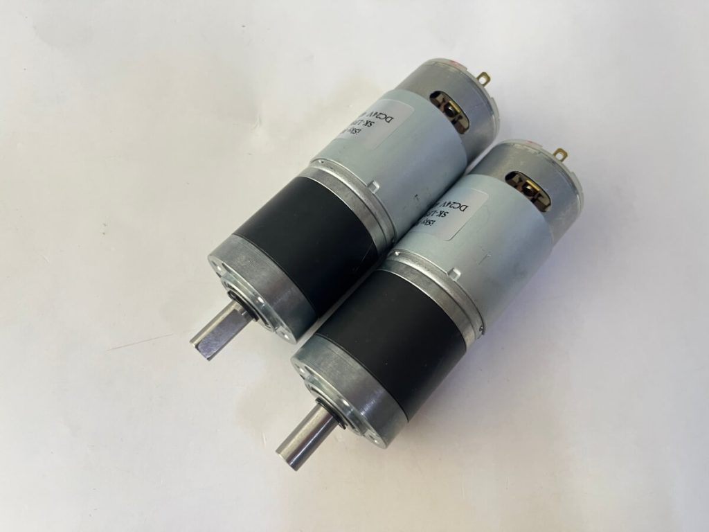
A quality dc planetary gear motor is defined by its tight dimensional tolerances, premium grade-five steel or hardened synthetic gears, and robust sealing systems. These manufacturing standards ensure that a premium dc planetary gear motor can deliver reliable torque for thousands of operating hours without internal degradation.
Premium Metallurgy and Materials
High-grade alloy steels and precision-molded polymers form the bedrock of premium gearboxes designed to resist tooth shearing. The choice of material dictates how well the gear teeth handle sudden shock loads.
Cheap materials will wear down in a matter of weeks, destroying the accuracy of your entire machine.
- Hardened Steel Gears: Ideal for high shock loads.
- Engineered Polymers: Perfect for ultra-quiet, lightweight setups.
Precision Manufacturing Tolerances
Minimal gear backlash is critical for applications requiring precise positioning, such as cameras or robotic steering. High-precision CNC machining ensures that gears align perfectly, eliminating noise and uneven tooth wear. Superior dual-bearing systems on the output shaft further stabilize the load.
Key Takeaway: Material choice and machining precision dictate whether a gearbox will survive under demanding industrial loads.
| Material Class | Shock Resistance | Noise Dampening | Component Cost | |
|---|---|---|---|---|
| Powdered Metal | Moderate | Moderate | Budget | |
| Hardened Steel | Excellent | Low | Premium | |
| Reinforced Nylon | Low | Excellent | Economical |
Evaluate materials carefully to balance cost with lifetime operating expectations.
How Do You Size a DC Planetary Gear Motor?
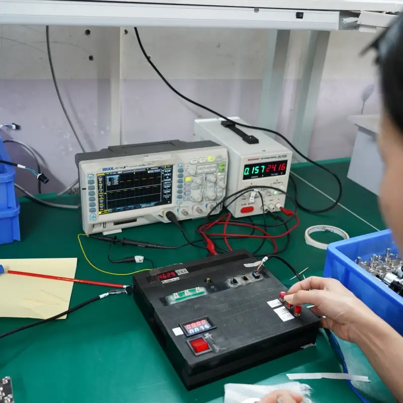
You size a dc planetary gear motor by calculating your application’s required continuous torque, peak startup torque, and target operating rotational speed. Matching these calculations to the performance curves of a dc planetary gear motor prevents premature motor burnout.
Torque Calculation Protocols
You must calculate both the steady-state running torque and the peak acceleration torque required to move the static load. Failing to account for initial mechanical inertia will result in an undersized motor.
Overlooking startup friction is the leading cause of drive systems failing right at the launch line.
- Static Torque: The force needed to overcome inertia.
- Dynamic Torque: The continuous energy required during travel.
RPM and Reducer Ratios
The input speed of the DC motor must match the gearbox reduction ratio to output the precise target RPM. Choosing the wrong ratio can force your motor to run outside its peak efficiency band, causing excess heat. The reduction ratio is calculated by dividing the input speed by your target output speed.
Key Takeaway: Accurate sizing ensures the motor operates efficiently without running hot or stalling under peak loads.
| Calculation Parameter | Unit | Primary Impact | Design Safety Factor | |
|---|---|---|---|---|
| Continuous Torque | Nm | Thermal Load | 1.2x – 1.5x | |
| Peak Startup Torque | Nm | Gear Strength | 1.5x – 2.0x | |
| Target Output RPM | RPM | Speed Profiles | Exact Match |
Always factor in a safety margin of at least twenty percent to account for unexpected mechanical resistance.
How to Maintain a DC Planetary Gear Motor?
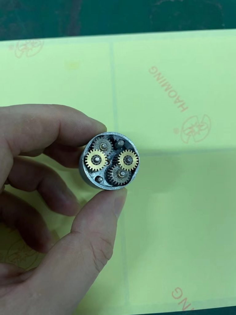
You maintain a dc planetary gear motor by performing periodic visual inspections, monitoring operating temperatures, and replenishing high-grade synthetic lubricants at scheduled intervals. Implementing these proactive steps ensures that your dc planetary gear motor maintains its high efficiency and avoids costly mechanical breakdowns.
Advanced Lubrication Protocols
The gear contact surfaces rely on a microscopic barrier of specialized synthetic grease to prevent direct metal-to-metal contact. Over time, heat and shearing forces degrade this protective layer.
Without this thin chemical layer, the gear teeth would quickly grind themselves into useless metal shavings.
- Fluorinated Greases: Exceptional for wide operational temperature ranges.
- Food-Grade Lubricants: Mandatory for medical or packaging equipment.
Wear and Thermal Inspections
Regularly checking the motor drawing current can help identify internal friction increases before they cause systemic damage. An unexpected spike in temperature often points to dry gear teeth or worn bearings that require immediate replacement. Keeping the housing clear of debris also aids natural heat dissipation.
Key Takeaway: Scheduled thermal checks and routine lubrication are key to preserving planetary gearbox integrity over years of service.
| Maintenance Task | Interval | Target Component | Benefit | |
|---|---|---|---|---|
| Temperature Check | Weekly | Gearbox Housing | Early Fault Detection | |
| Current Draw Analysis | Monthly | Motor Controller | Identifies Friction Spikes | |
| Lubrication Change | Annually | Internal Gears | Minimizes Wear & Tear |
Set up a predictive maintenance routine to capture abnormal thermal profiles before system failures occur.
Is a DC Planetary Gear Motor Quiet in Operation?
.jpg)
Yes, a dc planetary gear motor is remarkably quiet in operation when manufactured with high-precision helical gears and balanced planetary carriers. Utilizing specialized dampening materials allows a premium dc planetary gear motor to maintain low decibel levels even under high-torque conditions.
Helical vs Spur Gear Configuration
Helical gears feature angled teeth that engage gradually, which drastically reduces the structural vibration and harsh noise of direct impacts. This gradual contact spreads the load smoothly across the entire tooth face.
This gradual tooth engagement makes a massive difference in systems running near human operators.
- Helical Gear Geometry: Promotes smooth, quiet tooth transition.
- Spur Gear Geometry: High-torque capable but prone to louder whining noises.
Enclosure and Vibration Isolation
Using sound-absorbing synthetic housings and rubberized isolation mounts prevents motor vibrations from resonating through the main device. This acoustic dampening is vital for medical settings where quiet operation is non-negotiable. Precision alignment of the motor shaft also eliminates high-frequency mechanical hums.
Key Takeaway: Achieving quiet operation hinges on utilizing helical gear geometries alongside proper vibration dampening techniques.
| Gear Setup | Average Noise Level | Efficiency | Cost Factor | |
|---|---|---|---|---|
| Standard Spur | 55 – 65 dB | 75% | Low | |
| Straight Planetary | 45 – 55 dB | 85% | Medium | |
| Helical Planetary | Under 40 dB | 90% | High |
Helical planetary gearboxes are the optimal selection when low-decibel performance is a top project priority.
What Parts Make Up a DC Planetary Gear Motor?
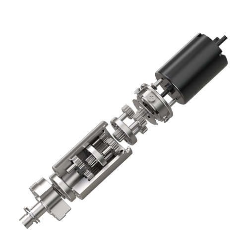
A dc planetary gear motor is made up of a central sun gear, several rotating planet gears, an outer ring gear, a planet carrier, and a robust driving DC motor unit. This concentric architecture allows a compact dc planetary gear motor to distribute torque evenly and achieve high reduction ratios in a small volume.
The Core Planetary Gear Components
The sun gear sits at the very center, driving the revolving planet gears which crawl along the static outer ring gear. This multi-point meshing distributes the structural load symmetrically around the central axis.
This design mimics a miniature solar system, ensuring that forces remain perfectly centered and balanced.
- Sun Gear: The central driver connected directly to the motor shaft.
- Planet Gears: Multiple gears that distribute the load and rotate around the sun.
The Carrier and Output Shaft
The planet carrier holds the planet gears in place and transmits their collective rotational force directly to the output shaft. This rigid linkage ensures that raw speed reduction translates directly into usable mechanical torque. Double ball bearings support the output shaft to absorb heavy radial and axial forces.
Key Takeaway: The concentric alignment of the sun, planets, and ring gears is the secret to high-torque density.
| Component Name | Primary Function | Stress Level | Critical Material Requirement | |
|---|---|---|---|---|
| Sun Gear | Inputs raw motor speed | High | Hardened steel | |
| Planet Gears | Distributes torque | High | High wear resistance | |
| Ring Gear | Guides planets externally | Moderate | Low dimensional distortion |
Ensure all components feature matched metallurgy to prevent uneven wear across different gear stages.
Can a DC Planetary Gear Motor Work in Mud?
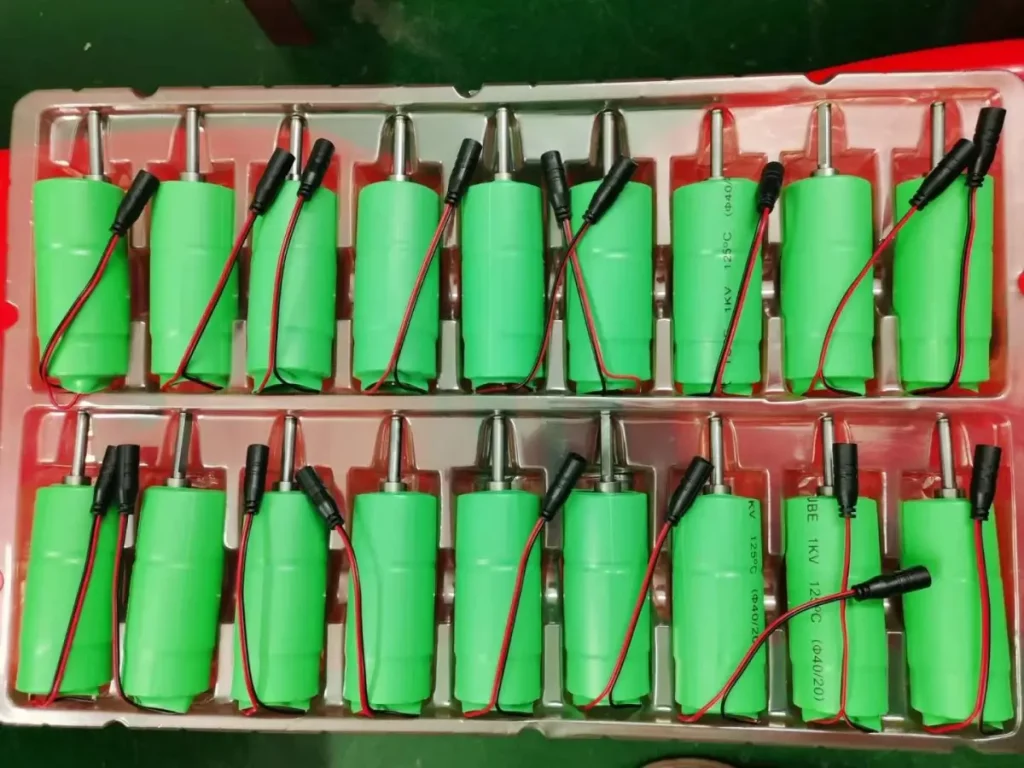
Yes, a dc planetary gear motor can work in mud, dust, and wet environments if it is built with an IP-rated protective enclosure and advanced rubber shaft seals. Specifying these heavy-duty seals ensures that a rugged dc planetary gear motor remains impervious to external contamination.
Ingress Protection Ratings
An IP65 or IP67 rating ensures that neither fine dust nor pressurized water jets can penetrate the gearbox housing. This level of protection is achieved by using precision-machined mating surfaces lined with synthetic gaskets.
Without adequate sealing, grit will act like sandpaper, quickly grinding down the gears and destroying the motor windings.
- IP65 Rating: Dust-tight and resistant to water splashes.
- IP67 Rating: Completely dust-tight and submersible in shallow water.
Specialized Shaft Seals
Double-lip rotary shaft seals keep internal lubricants locked inside while preventing liquid mud and fine particulate ingress. These seals must be made of high-wear synthetic rubbers like Viton to survive high rotational speeds. Additionally, a corrosion-resistant stainless steel shaft prevents oxidation from degrading the seal contact area.
Key Takeaway: Rugged environmental protection relies on high-quality IP sealing and durable rotary shaft seals.
| IP Rating | Dust Protection | Liquid Protection | Optimal Environment | |
|---|---|---|---|---|
| IP54 | Limited protection | Resists light splashes | Indoor factories | |
| IP65 | Fully dust-tight | Resists low-pressure jets | Dusty warehouses | |
| IP67 | Fully dust-tight | Submersible (1 meter) | Outdoor mud & rain |
Specify an IP67 rated planetary assembly for any outdoor agricultural or heavy industrial application.
Why Does a DC Planetary Gear Motor Run Hot?
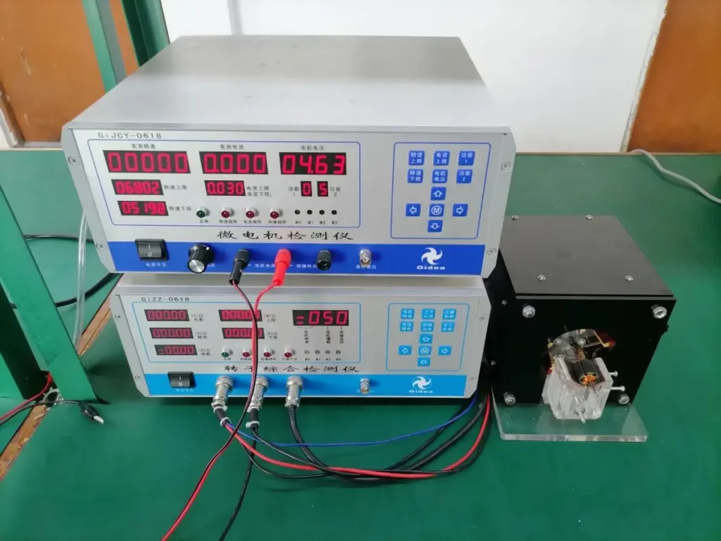
A dc planetary gear motor runs hot when it is operated beyond its continuous duty cycle, experiences excessive mechanical binding, or lacks proper ventilation. Addressing these heat sources promptly prevents thermal damage to your dc planetary gear motor.
Overloading and Excessive Friction
Operating the motor above its rated torque forces the windings to draw excessive electrical current, which generates intense heat. If the gears are misaligned or packed with degraded, dry lubricant, internal friction increases significantly.
Continuous overloading can melt the thin insulation on the copper coils, causing a catastrophic short-circuit.
- Stall Conditions: Generates maximum current draw and rapid heat spikes.
- Over-greasing: Causes internal viscous drag, raising operating temperatures.
Thermal Management Systems
Adding aluminum heatsinks and ensuring adequate natural convection currents helps dissipate heat away from the motor body. For enclosed spaces, forced air cooling or thermal interface pads can prevent thermal runaway. Thermistors can also be integrated into the winding assembly to monitor temperatures and trigger automatic shutoffs.
Key Takeaway: Uncontrolled heat generation is primarily driven by current overload, mechanical binding, or poor heat dissipation.
| Heat Root Cause | Diagnostic Method | Recommended Correction | |
|---|---|---|---|
| Electrical Overload | Current clamp meter check | Reduce load or increase gear ratio | |
| Dry Gear Lubrication | Acoustic hum & vibration | Clean and apply synthetic grease | |
| Poor Ventilation | Thermal camera imaging | Install heatsinks or cooling vents |
Always monitor case temperatures during testing to ensure the motor operates within safe thermal limits.
High-Performance Drive Systems Built for Your Toughest Demands
Selecting the correct drive solution dictates the ultimate performance, longevity, and commercial success of your automation projects. At iSky Motor, we engineer elite-grade motion control systems tailored precisely to your specific load, speed, and spatial parameters. Our dedication to premium metallurgy, state-of-the-art helical planetary geometries, and reliable environmental sealing ensures your machines operate flawlessly in the field. Let us transform your complex engineering challenges into smooth, quiet, and incredibly efficient mechanical movements. For custom configurations, detailed CAD designs, and expert technical support, contact us today to discuss your project requirements and discover how our advanced motion technologies can elevate your business.
Frequently Asked Questions
Can I run a DC planetary gear motor in reverse?
Yes, you can easily reverse the rotation by swapping the positive and negative electrical leads. Because planetary systems are structurally symmetrical, they deliver identical torque performance in both clockwise and counter-clockwise directions.
What’s the best way to prevent gear stripping?
The best way is to specify hardened steel gears and include an electronic current-limiting controller. Restricting the peak current prevents the motor from generating transient torque spikes that exceed the yield strength of the gear teeth.
Can I run this motor continuously at its peak torque rating?
No, peak torque is strictly rated for intermittent startup or acceleration cycles only. Continuous operation at peak levels causes extreme thermal build-up that will quickly degrade internal windings and lubricants.
What’s the best lubrication for low temperatures?
The best option is a low-viscosity synthetic fluorinated grease formulated to maintain its fluid properties below freezing. Standard greases thicken in cold temperatures, creating massive viscous drag that overloads the motor.
Can I use a planetary motor as a high-precision encoder?
No, the motor itself cannot act as an encoder, but you must pair it with a rear-mounted optical or magnetic encoder. This setup allows you to track output shaft rotation precisely despite any minimal mechanical backlash in the gearbox.