
A planetary gearbox is a highly efficient speed reduction system that works by revolving multiple planet gears around a central sun gear, and it consists of components such as the sun gear, planet gears, a planet carrier, and an outer ring gear. Many B2B design engineers suffer from lost system performance and strict space constraints when developing automated machinery. Relying on bulky, outdated motors that wear out prematurely under heavy continuous loads leads to expensive downtime and constant maintenance.
Fortunately, upgrading your systems with a high-performance gearbox motor solves these power transmission problems by providing unmatched torque density in an incredibly compact space. This advanced configuration ensures smooth, quiet, and exceptionally reliable performance for your most demanding industrial applications.
What Is a Planetary Gearbox and Why Is It Named This Way?
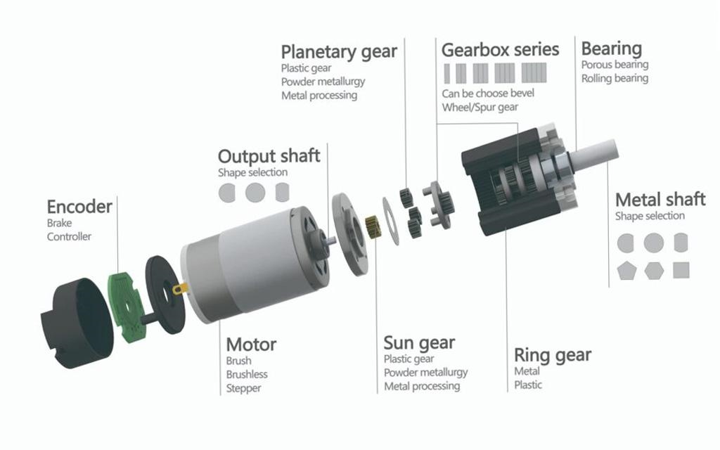
A planetary gearbox is a specialized gear reduction assembly named after its unique structural resemblance to the solar system, where gears orbit a central point. This highly efficient design allows a miniature gearbox motor to handle immense torque loads while maintaining a small physical footprint. By distributing mechanical loads across multiple gear teeth, it minimizes friction and maximizes operating life.
Industrial automation systems rely heavily on this configuration to achieve seamless power transmission in tight spaces. Its compact architecture makes it the gold standard for high-performance motion control.
How does the solar system analogy apply here?
In this mechanical system, the central sun gear acts as the system’s “star” while the planet gears orbit around it. The outer ring gear serves as the stationary boundary, keeping the planetary orbits perfectly aligned.
- Central Sun Gear: Inputs the initial high-speed rotational force.
- Orbiting Planet Gears: Revolve and rotate to transfer torque.
- Outer Ring Gear: Provides the internal teeth boundary for meshing.
This orbit-like movement allows multiple teeth to engage simultaneously. Consequently, the load is divided, reducing wear on individual components.
Why is power density critical for B2B designs?
B2B manufacturers require maximum power in the smallest possible physical housing. Traditional spur gearboxes are far too bulky for modern compact machinery.
- Space Savings: Eliminates the need for massive, multi-shaft gear trains.
- Weight Reduction: Decreases structural load on robotic joints.
- High Efficiency: Achieves up to 97% power transmission efficiency.
Selecting an optimized gearbox motor ensures your product meets modern space constraints without sacrificing torque. It provides the competitive edge your engineering projects need.
Key Takeaway: For B2B engineering teams, selecting a high-density gearbox motor reduces the overall physical envelope of your product line. This directly lowers shipping costs and allows your machines to fit into tightly constrained factory floors. Ultimately, it delivers superior power efficiency that offsets long-term operational expenses.
| Feature | Planetary Gearbox | Traditional Spur Gearbox | |
|---|---|---|---|
| Power Density | Extremely High | Low to Moderate | |
| Load Distribution | Shared among multiple gears | Borne by a single tooth mesh | |
| Backlash Risk | Very Low | High |
Analyzing the structural differences above highlights why planetary gearboxes are the preferred choice for high-precision B2B automation.
How Does a Planetary Gearbox Transmit Torque and Power?
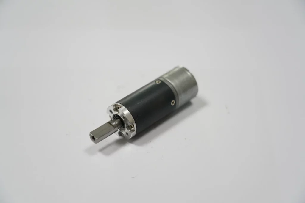
A planetary gearbox transmits torque and power by distributing the input rotational force from the sun gear to multiple planet gears meshed with an outer ring gear. This balanced distribution enables a high-torque gearbox motor to process heavy loads with unmatched rotational precision. By keeping forces radial, the system minimizes axial stress on your motor bearings.
When the input shaft spins the sun gear, the planet gears are forced to roll along the internal circumference of the ring gear. This motion drives the planetary carrier, which then outputs high-torque, low-speed rotation.
How do load-sharing mechanics actually work?
Unlike standard gears that mesh at a single point, planetary systems share the operating load across several planet gears.
- Load Division: Divides total torque by the number of planet gears (typically 3 or 4).
- Stress Reduction: Lowers surface pressure on gear teeth by up to 300%.
- Deflection Prevention: Eliminates bending stress on the shafts.
This multi-point contact prevents teeth from breaking under sudden shock loads. Your machinery gains exceptional reliability during high-duty cycles.
What causes high efficiency in these gears?
High efficiency stems from pure rolling motion and minimal sliding friction between the mating gear teeth.
- Symmetric Design: Balances internal forces to prevent energy losses.
- In-line Shafts: Aligns input and output shafts directly to maximize axial throughput.
- Optimized Lubrication: Retains oil or grease effectively within the enclosed casing.
Because little energy is wasted as heat, the overall system runs much cooler. This ensures the connected motor operates within its ideal thermal zone.
Key Takeaway: Understanding how torque is distributed allows B2B buyers to select systems that survive heavy continuous cycles. Shared loading ensures high efficiency and avoids premature gear failure in demanding environments.
| Metric | Load Sharing System | Single-Mesh System | |
|---|---|---|---|
| Efficiency Rate | 95% – 98% | 80% – 90% | |
| Shock Load Capacity | Outstanding | Poor | |
| Thermal Generation | Minimal | Moderate to High |
Evaluating these parameters clarifies how multi-contact gear geometry maintains peak performance during heavy-duty operations.
What Critical Role Does the Central Sun Gear Play?
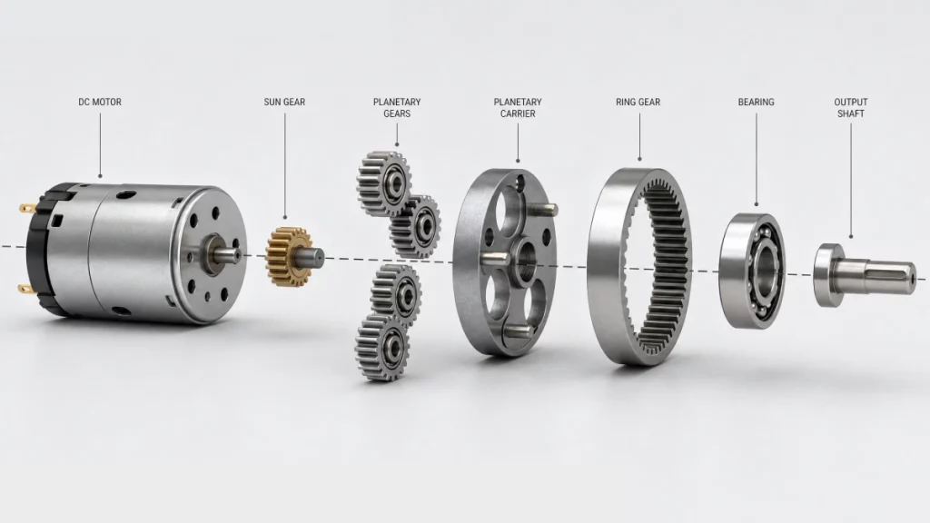
The central sun gear acts as the primary driver of the planetary gearbox, directly receiving the rotational input from the motor. It is the core input mechanism that transmits torque to the revolving planet gears. In any miniature gearbox motor design, the sun gear must withstand high torsional forces.
Because it is the smallest gear in the system, it rotates at the highest speed. This makes its material quality and precision-cut teeth absolutely critical.
Is the sun gear always the main input?
Yes, in standard speed reduction applications, the sun gear serves as the primary input component.
- Speed Reduction: High input speed at the sun gear yields slow output speed at the carrier.
- Torque Multiplication: Drives the larger planet carrier to multiply torque output.
- Direction Control: Controls clockwise or counterclockwise output direction.
Changing which component is held stationary can alter the gear ratio. However, standard industrial systems almost exclusively drive the sun gear for reduction.
How does tooth precision affect durability?
Precision-cut teeth are mandatory to prevent microscopic alignment issues from escalating into complete gear failures.
- Backlash Prevention: Highly accurate profiles keep backlash to an absolute minimum.
- Noise Reduction: Smooth engagement quietens the entire gear train.
- Wear Minimization: Prevents uneven stress concentration across the gear face.
A poorly machined sun gear will quickly wear down the surrounding planet gears. Ensuring high precision guarantees years of maintenance-free operation.
Key Takeaway: Investing in a sun gear with superior tooth precision is vital for high-precision positioning systems. It directly reduces backlash and prevents micro-vibrations from damaging your sensitive equipment.
| Gear Class | Backlash Performance | Target B2B Application | |
|---|---|---|---|
| Precision Ground | < 3 arc-min | Robotics & Medical Robotics | |
| Standard Cut | 10 – 15 arc-min | General Conveyors & Mixers | |
| Molded Plastic | > 25 arc-min | Low-cost Consumer Devices |
Comparing gear classes reveals that high-precision grinding is crucial for medical and robotic automation.
How Does the Outer Ring Gear Keep the System Stable?
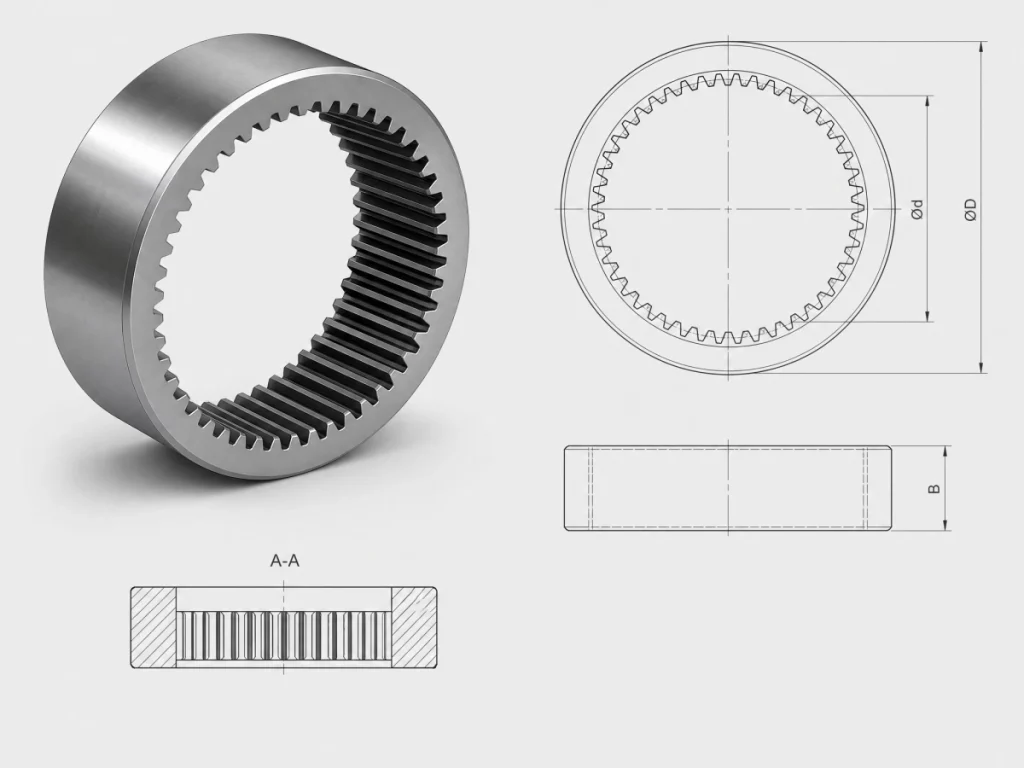
The outer ring gear keeps the system stable by acting as the rigid outer boundary that keeps the planet gears perfectly aligned. This component is essential for reinforcing the structural integrity of your high-torque gearbox motor system. By enclosing the moving parts, it also doubles as a protective outer housing.
It features internal teeth that mesh directly with the outer faces of the orbiting planet gears. Without this outer ring, the planetary constellation would lose its spatial reference and fail to transmit power.
Is the ring gear always held stationary?
In the vast majority of industrial speed reducers, the outer ring gear is indeed fixed to the gearbox casing.
- Stationary Reference: Holding it still forces the planet gears to walk around the sun.
- Rotational Dynamics: Allows the carrier to turn in the same direction as the sun gear.
- Differential Drives: In rare cases, rotating the ring gear allows for complex speed summing.
Keeping the ring gear stationary ensures maximum mechanical advantage. This setup simplifies mounting configurations for industrial machinery builders.
How does internal teeth engagement work?
The internal teeth of the ring gear curve inward to wrap around the planet gears.
- High Contact Ratio: More teeth mesh simultaneously compared to external gear sets.
- Inward Curved Geometry: Naturally guides the planet gears along a perfect circular path.
- Even Stress Distribution: Absorbs and dampens intense radial forces.
This curved, internal contact maximizes the contact surface area during power transmission. This minimizes tooth bending stress during high shock loads.
Key Takeaway: Choosing a ring gear made from high-strength hardened steel ensures your system survives high torque reversals. A robust outer ring prevents housing deformation and extends overall gearbox life.
| Ring Gear Material | Hardness Rating | Shock Resistance | |
|---|---|---|---|
| Hardened Alloy Steel | 58 – 62 HRC | Exceptional | |
| Sintered Powder Metal | 35 – 45 HRC | Moderate | |
| Reinforced Nylon | N/A | Low |
Choosing the correct material grade ensures your machinery remains stable under unpredictable shock load spikes.
Why Is the Planet Carrier the Backbone of the Gearbox?
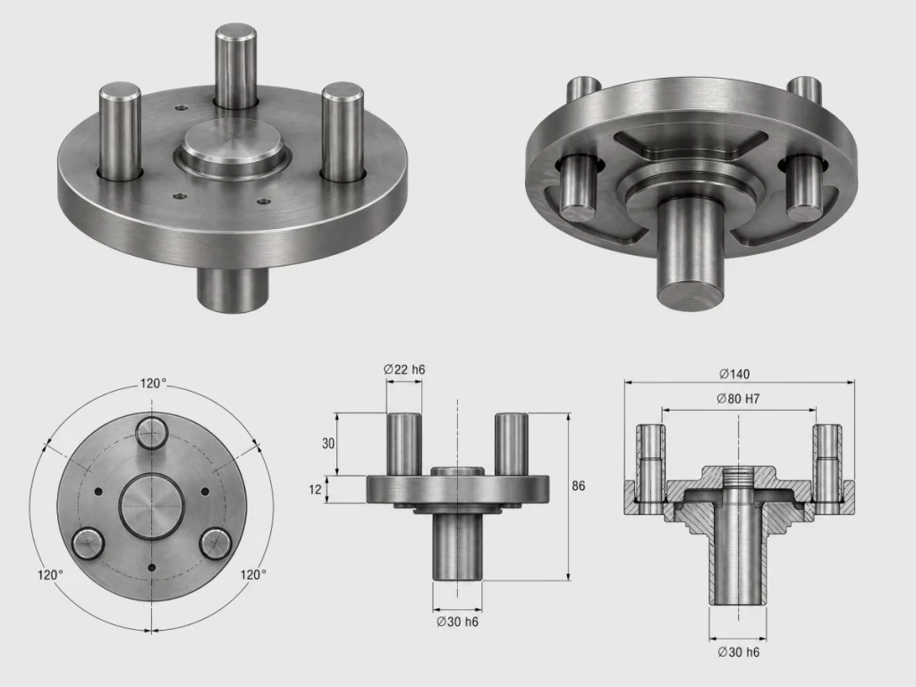
The planet carrier serves as the backbone of the gearbox by securing the planetary gears in place and transmitting their collective rotation directly to the output shaft. It acts as the mechanical bridge that gathers individual torque contributions from the orbiting planet gears inside the gearbox motor. Its structural rigidity directly dictates the torsional stiffness of the entire assembly.
If the carrier is weak, it can bend under high torque, causing misalignment of the planet gears. This misalignment leads to rapid gear wear and eventual catastrophic system failure.
How does the carrier distribute stress?
The carrier features multiple precision-machined pins that hold each planet gear securely in place.
- Equal Spacing: Spaces the planet gears at exact angular intervals (e.g., 120 degrees).
- Torque Summation: Combines the forces of all planets into a single output force.
- Radial Balance: Cancels out radial forces to protect the output shaft bearings.
Because it balances out radial stresses, only pure torsional energy is delivered to the output. This results in smoother rotation under varied loads.
Why does structural material matter here?
The planet carrier must be constructed from high-tensile materials to resist twisting under extreme loads.
- Ductile Iron: Offers excellent vibration damping and fatigue limits.
- Carbon Steel: Provides high yield strength for heavy industrial gearboxes.
- Anodized Aluminum: Reduces rotational inertia in high-speed micro systems.
Choosing the wrong carrier material can lead to torsional deflection. High-tensile steel carriers are recommended for applications requiring precise start-stop positioning.
Key Takeaway: Selecting gearboxes with robust, steel-cast planet carriers protects your machinery from alignment drift. This ensures long-term positional accuracy in high-speed pick-and-place applications.
| Carrier Material | Yield Strength (MPa) | Rotational Inertia | Best For | |
|---|---|---|---|---|
| Cast Iron / Steel | 450 – 650 | High | Heavy Duty / High Load | |
| Alum. Alloy (7075) | 500 | Low | High Acceleration | |
| Engineered Plastics | 80 | Extremely Low | Low Cost / Light Duty |
Analyzing material properties helps design engineers balance structural strength and system responsiveness.
What Does an Exploded View Reveal About Internal Fit?
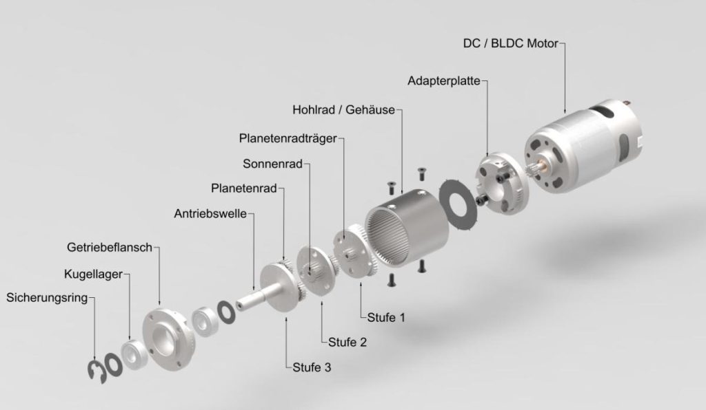
An exploded view reveals the precise alignment and critical placement of every internal component, showing how they fit together to prevent friction and backlash. Examining this internal arrangement allows engineers to understand how a micro gearbox motor achieves high mechanical efficiency. Each spacer, shim, and bearing must sit in its exact designated position.
Proper component stacking prevents internal gears from shifting axially during intense operation. It is this minute engineering precision that separates industrial-grade gearboxes from low-quality alternatives.
What is the correct alignment sequence?
Assembling a planetary gearbox requires a strict sequence of steps to maintain structural stability.
- Central Alignment: Center the sun gear on the motor drive shaft.
- Constellation Fit: Mesh the planet gears on the carrier pins before housing insertion.
- Ring Gear Integration: Slide the planetary cluster smoothly into the internal ring teeth.
Forcing any component during this assembly sequence can introduce micro-cracks. A smooth, slip-fit assembly ensures maximum service life.
How do bearings and seals prevent failures?
Deep-groove ball bearings and double-lip rubber seals act as the first line of defense against environmental hazards.
- Shaft Support: Ball bearings keep the input and output shafts perfectly concentric.
- Grease Retention: Keeps high-performance lubricants locked inside the gear chamber.
- Contaminant Exclusion: Prevents abrasive dust, grit, and moisture from entering.
If a seal fails, oil leakage will lead to rapid dry friction and metal grinding. Using premium seals extends the gearbox’s maintenance-free operational life.
Key Takeaway: Specifying high-quality seals and bearings prevents oil leakage and dust ingress. This dramatically reduces maintenance callouts in challenging industrial environments.
| Seal/Bearing Type | Max Speed (RPM) | Protection Level | Maintenance Need | |
|---|---|---|---|---|
| Sealed Ball Bearing | 12,000 | Excellent | Maintenance-Free | |
| Bronze Bushing | 3,000 | Moderate | Periodic Lubrication | |
| Double-Lip Oil Seal | N/A | IP65 Dust/Water | Replace after 10k hrs |
Reviewing seal specifications helps identify models capable of surviving wet or dusty outdoor conditions.
Why Should B2B Engineers Choose a Compact Gearbox Motor?
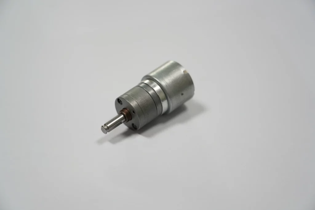
B2B engineers should choose a compact gearbox motor because it delivers outstanding torque multiplication and speed reduction while fitting into highly constrained device designs. This space-saving design makes the modern gearbox motor the top choice for smart medical devices, robotic arms, and high-tech warehouse AGVs. Integrating the motor and gearbox into a single housing eliminates alignment errors.
It also cuts assembly time in half during your production runs. Instead of mounting separate components, you install a pre-aligned, fully tested power unit.
What makes a compact design so efficient?
Merging the motor shaft directly with the sun gear eliminates the need for flexible couplings.
- Zero Mechanical Backlash: Direct mating eliminates rotational play.
- Reduced Total Weight: Eliminates bulky brackets and external connectors.
- Enhanced Torque Density: Delivers high mechanical power relative to volume.
This streamlined design ensures that motor energy is converted directly into useful mechanical work. It reduces power drain in battery-operated applications.
How does it reduce your spatial footprint?
Standard motors with inline spur gears extend significantly outward, taking up valuable machine depth.
- Concentric Alignment: Keeps the motor and output shaft on the same center line.
- Compact Length: Reduces overall length by up to 40% compared to spur gearboxes.
- Symmetrical Housing: Allows for mounting at any rotational angle.
This enables product designers to slim down their machine outer dimensions. A sleeker product is easier to market and sell to your customers.
Key Takeaway: Selecting pre-integrated compact motors cuts down your bill-of-materials and guarantees flawless shaft alignment. This lowers overall design risks and accelerates your product launch timelines.
| Parameter | Pre-Integrated System | Separate Motor + Gearbox | |
|---|---|---|---|
| Assembly Time | < 5 Minutes | 30 – 45 Minutes | |
| Alignment Risk | Zero (Factory Pre-Aligned) | Moderate to High | |
| Total Length | Highly Compact | Extended Shaft Couplers |
Comparing these assembly options highlights the dramatic time and cost savings achieved through integration.
How Do Single and Multi-Stage Systems Compare?
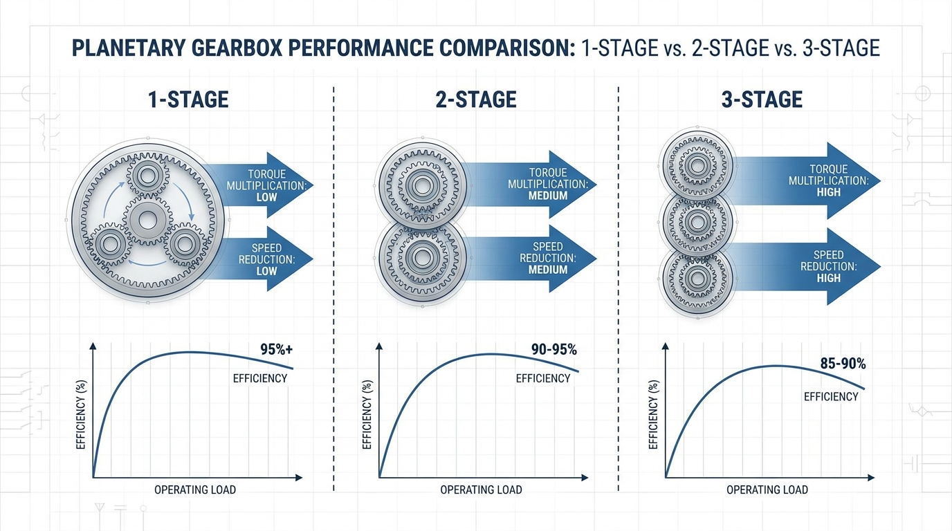
Single and multi-stage systems compare by stacking planetary gear sets to achieve increasingly higher gear reduction ratios within the same radial envelope. Stacking these stages allows a high-performance gearbox motor to multiply its torque output exponentially. However, adding more stages introduces minor efficiency trade-offs.
Each additional stage increases internal friction and adds slight physical length to the gearbox housing. Understanding this trade-off is crucial when designing precision drive systems.
What are single-stage ratio limitations?
A single-stage planetary gearbox is generally limited to gear ratios between 3:1 and 10:1.
- Tooth Size Constraints: Sun gear becomes too small if the ratio is too high.
- Interference Issues: Planet gears will clash if they are designed too large.
- Efficiency Peak: Single-stage systems achieve the highest efficiency, often above 97%.
If your application requires a massive speed drop, a single stage simply will not suffice. Forcing extreme ratios into one stage compromises tooth strength.
When should you opt for multi-stage gearboxes?
You should choose a multi-stage configuration when your application demands heavy torque multiplication at low output speeds.
- High Reduction Ratios: Easily achieves ratios from 15:1 up to 500:1 or more.
- Stacked Power: The output shaft of the first stage drives the sun gear of the second stage.
- Compact Length Scaling: Only increases length slightly while maintaining identical diameter.
Multi-stage systems are ideal for high-load conveyor systems, lifting winches, and precise valve actuators. They give you maximum torque output in a minimal radial profile.
Key Takeaway: Choosing the correct stage configuration ensures you achieve the exact balance of torque and output speed. This maximizes mechanical efficiency while keeping the motor within its prime operating speed.
| Stage Configuration | Typical Gear Ratio Range | Mechanical Efficiency | Relative Length | |
|---|---|---|---|---|
| 1-Stage | 3:1 – 10:1 | 95% – 98% | Shortest | |
| 2-Stage | 12:1 – 100:1 | 90% – 95% | Medium | |
| 3-Stage | 100:1 – 500:1+ | 85% – 90% | Longest |
Evaluating these parameters helps engineers decide whether to prioritize raw speed reduction or maximum power throughput.
What Are the Best Practices for Gearbox Lubrication?
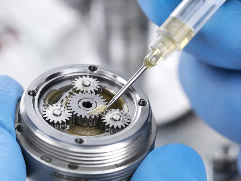
The best practices for gearbox lubrication involve selecting the correct fluid viscosity and scheduling regular oil checks to prevent metal-on-metal contact. Proper lubrication is the single most important factor in extending the operational lifespan of your gearbox motor. Without a high-quality lubricating barrier, friction will quickly destroy the gear teeth.
Choosing between synthetic grease and lubricating oil depends directly on your system’s operating speed and ambient temperatures. High-temperature environments require advanced formulations to prevent chemical breakdown.
Which lubricants ensure thermal stability?
Synthetic lubricants containing specialized extreme pressure (EP) additives offer the highest level of thermal stability.
- Viscosity Index: Synthetics maintain stable thickness across extreme temperatures.
- Shear Resistance: Resists molecular breakdown under intense gear-meshing stress.
- Antioxidant Properties: Prevents sludge and varnish formation at high operating loads.
Using standard mineral oils can result in lubrication thinning, leading to gear grinding. Synthetic grease is highly recommended for lifetime-lubricated micro gearboxes.
How often should maintenance be performed?
Maintenance schedules vary based on the intensity of your industrial duty cycle.
- Continuous Duty: Inspect lubricant levels every 2,500 hours of run time.
- Intermittent Duty: Check for seal leaks and clean the housing annually.
- Lifetime Sealed Units: Often require zero maintenance under rated operating conditions.
Early detection of oil darkening or metal flakes prevents catastrophic failures. Implementing predictive oil analysis ensures maximum uptime for your factory.
Key Takeaway: Adopting synthetic lubricants and setting proactive maintenance intervals shields your system from thermal wear. This simple step keeps your automated production lines running smoothly year-round.
| Lubricant Class | Operating Temp Range | Main Benefit | Expected Life | |
|---|---|---|---|---|
| Synthetic Grease | -40°C to 150°C | No Leaks / Maintenance-Free | 5,000+ Hours | |
| Synthetic EP Oil | -30°C to 120°C | Superior Cooling Capacity | 3,000 Hours | |
| Standard Mineral Oil | -10°C to 80°C | Economical Cost | 1,000 Hours |
Comparing these lubrication classes helps engineers determine the most cost-effective maintenance strategy for their operational climate.
How Do You Select the Right Miniature Gearbox Motor?
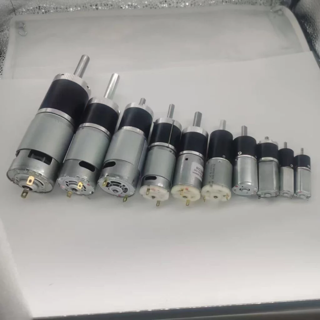
You select the right miniature gearbox motor by matching your application’s required output torque, operating speed, and physical dimensions with the proper motor chemistry. Choosing a high-quality gearbox motor involves evaluating the electrical performance alongside the mechanical gear capabilities. Ensuring these elements match prevents motor overloading.
Working with an experienced manufacturer like iSky simplifies this complex engineering selection process. Their diverse portfolio covers brushless, brushed, and specialized miniature gear systems.
What role do brushless motors play?
Brushless DC (BLDC) motors offer maximum efficiency, long life, and precise speed control.
- No Brush Wear: Eliminates brush maintenance, sparking, and electrical noise.
- High Efficiency: Converts up to 90% of electrical power into mechanical rotation.
- Thermal Control: Dissipates heat better because windings are on the stator.
When paired with a planetary gearbox, BLDC motors create an incredibly durable drive solution. This combination is ideal for high-duty cycle applications like robotic joints.
How do you calculate your torque requirements?
Calculating required torque involves multiplying the load mass by the radius of rotation and adding an acceleration safety margin.
- Calculate Static Load: Torque required to hold the load in place.
- Calculate Dynamic Torque: Torque needed to accelerate the load to operating speed.
- Apply Safety Factor: Typically add 20% to 50% to handle unexpected friction spikes.
Selecting a motor without these calculations leads to overheating or failure to start. Always consult with an application engineer to verify your calculations.
Key Takeaway: Partnering with a custom manufacturer like iSky ensures your miniature gear motor is custom-tailored to your exact torque and space constraints. This eliminates expensive design overruns and ensures reliable, long-term field operation.
| Motor Type | Rated Life (Hours) | Speed Range (RPM) | Torsional Stiffness | |
|---|---|---|---|---|
| Brushless DC (BLDC) | 15,000+ | 1,000 – 20,000 | Excellent | |
| Brushed DC | 2,000 – 5,000 | 1,000 – 10,000 | Moderate | |
| Stepper Motor | 10,000+ | 100 – 3,000 | High (at low speeds) |
Analyzing motor types and lifespans is the first step in ensuring your machine meets its target warranty periods.
Conclusion
Selecting the perfect planetary gear system is critical to maximizing the torque density and operational lifetime of your industrial automation equipment. At iSky, we specialize in manufacturing premium, high-efficiency miniature DC gear motors, including advanced brushless options and highly durable planetary gearheads. Our engineering team stands ready to customize the ideal motor configuration to match your exact spatial and performance requirements.
Do not let power constraints or bulky motors hold your product designs back. To discuss your project specifications and receive a customized quote, contact us today to partner with our motion control experts.
FAQ Section
Can I run a planetary gearbox in both directions?
Yes. Reversing the rotational direction of the input motor will instantly reverse the output rotation of the gearbox without damaging any internal gears. This capability is standard and highly reliable for bidirectional applications.
What’s the best way to handle excessive gearbox noise?
Check the lubrication levels and gear alignment immediately. Excessive noise is typically a sign of dry friction, microscopic gear misalignment, or worn-out bearings. Adding high-performance synthetic grease will usually restore quiet operation.
How do I know if my planetary gearbox is overloaded?
Monitor the operating temperature and listen for unusual vibrations or whining sounds. If the casing feels hot to the touch or if the motor begins drawing excessive current, you have likely exceeded the rated torque limit. You should immediately reduce the load or upgrade to a higher-capacity stage model.
Can I use plastic planetary gears for industrial B2B machines?
No, steel gears are recommended for industrial use. While engineered plastic gears perform exceptionally well in low-cost consumer electronics, they lack the torsional strength and heat dissipation required for high-torque industrial machinery. Hardened metal gears are essential to ensure long-term durability in high-duty environments.