
The primary types of gearboxes are spur, planetary, worm, helical, and flat, which serve to adjust output torque and speed for specific industrial applications. If you are an industrial OEM, finding the perfect balance between motor speed and mechanical torque is a constant engineering headache. Using mismatched power transmission components leads to premature system wear, excessive power draw, and costly operational downtime. Fortunately, integrating a high-performance motor gearbox solves this challenge by efficiently bridging the gap between high motor speeds and high torque demands.
What Are the Main Types of Gearboxes?
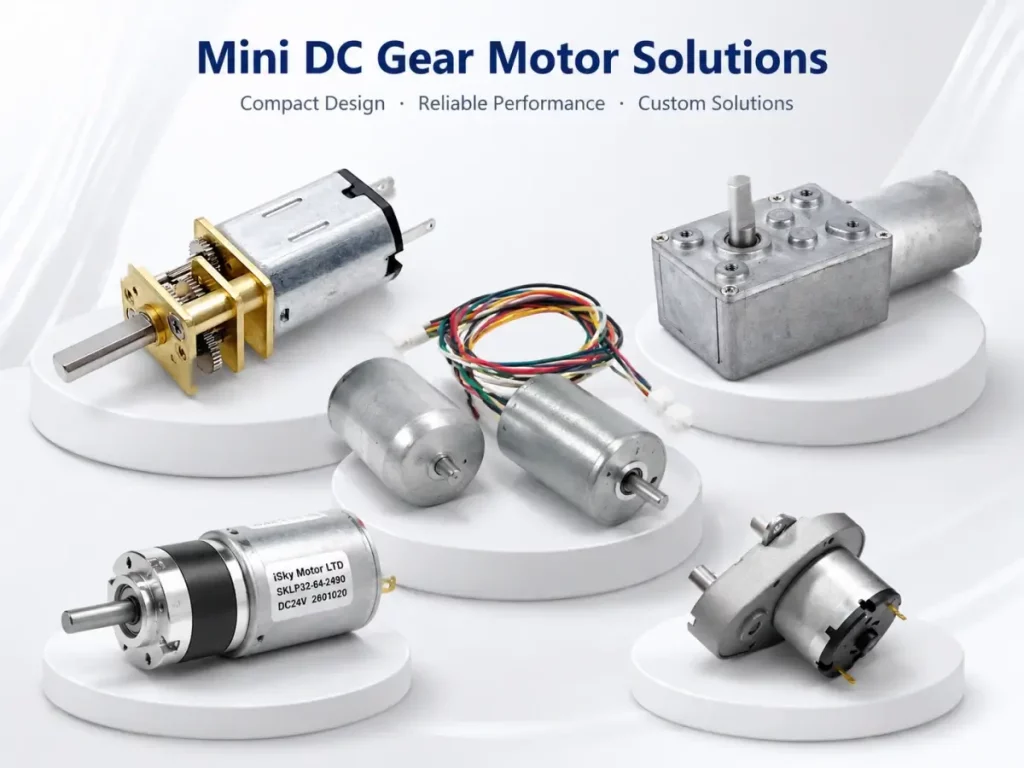
The main types of gearboxes include spur, planetary, worm, helical, and flat gearboxes, each utilizing unique gear geometry to transmit rotational power. They work by trading motor speed for mechanical torque, which allows standard motors to operate at their peak efficiency ranges. Integrating a robust motor gearbox into your system is key to managing these dynamic loads.
The Fundamentals of Speed and Torque
Electric motors naturally run most efficiently at high speeds, typically exceeding 1,000 RPM. However, most industrial automation applications require much slower speeds paired with heavy driving force. Adding a gear reduction stage allows the motor to spin fast and efficiently while the output shaft turns slow and strong.
- High efficiency: Operating at nominal RPM prevents winding overheat.
- Controlled speed: Delivers smooth motion for conveyors and actuators.
How do they compare? This speed-to-torque trade-off remains the cornerstone of modern mechanical engineering.
Why Geometric Configuration Matters
Different mechanical setups align the input and output shafts in distinct orientations to fit specific space envelopes. Aligning these shafts correctly prevents excessive radial and axial wear on your internal bearings. Here is what this means for your machine design:
- Inline shafts: Best for planetary and coaxial helical gearboxes.
- Parallel offset shafts: Typically found in spur and flat gear designs.
- Right-angle shafts: Common in worm and bevel helical systems.
| Gearbox Type | Shaft Alignment | Efficiency Range | Key Benefit | |
|---|---|---|---|---|
| Planetary | Coaxial Inline | 90% – 98% | High torque density | |
| Worm | 90-Degree Right-Angle | 50% – 90% | Excellent self-locking | |
| Spur | Parallel Offset | 85% – 95% | Simple and cost-effective |
The table highlights that inline systems offer the highest efficiency, whereas right-angle setups trade some performance for critical space and safety advantages. Key Takeaway: Selecting the right gearbox configuration is not just about power, but matching physical alignment constraints with mechanical efficiency requirements.
How Do Spur Gearboxes Deliver Value?
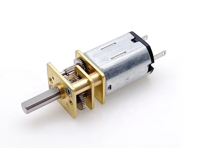
Spur gearboxes deliver value by utilizing straight-cut teeth parallel to the shaft to offer a highly cost-effective and reliable speed reduction solution. Pairing a high-quality motor gearbox with parallel shafts ensures straightforward power transmission without introducing axial forces. This elegant design keeps production costs exceptionally low.
The Mechanics of Straight-Cut Gears
Spur gears feature teeth machined parallel to the rotational axis on a circular body. These gears mesh one tooth at a time, making them incredibly simple to manufacture and maintain over long lifecycles.
- Straight-cut teeth: Mesh instantly to transmit maximum torque directly.
- Simple maintenance: Straightforward alignment minimizes runtime errors.
What is the catch? This single-tooth contact pattern can lead to elevated noise levels at extreme rotational speeds.
Applications of Spur Gear DC Motors
When integrated into compact systems, a spur gear setup excels in low-duty cycle environments. They are ideal for applications requiring simple, straight-line power transfer.
- Vending systems: Reliable mechanical vending drawer slideouts.
- Office equipment: Low-load printer paper rollers and document feeders.
- Lab devices: Precise automated fluid vial handling carousels.
| Parameter | Spur Gearbox | Alternative Options | |
|---|---|---|---|
| Relative Cost | Very Low | Moderate to High | |
| Noise Level | Higher at High RPM | Lower/Quieter | |
| Shaft Position | Parallel Offset | Centered/Coaxial |
The comparison demonstrates that while spur gearboxes are highly cost-efficient, they may generate more operational noise at higher speeds compared to other designs. Key Takeaway: Spur gearboxes are the most economical option for low-speed and low-duty applications where maximum noise suppression is not the primary engineering goal. Is there an alternative?
Why Choose a Planetary Gearbox Design?
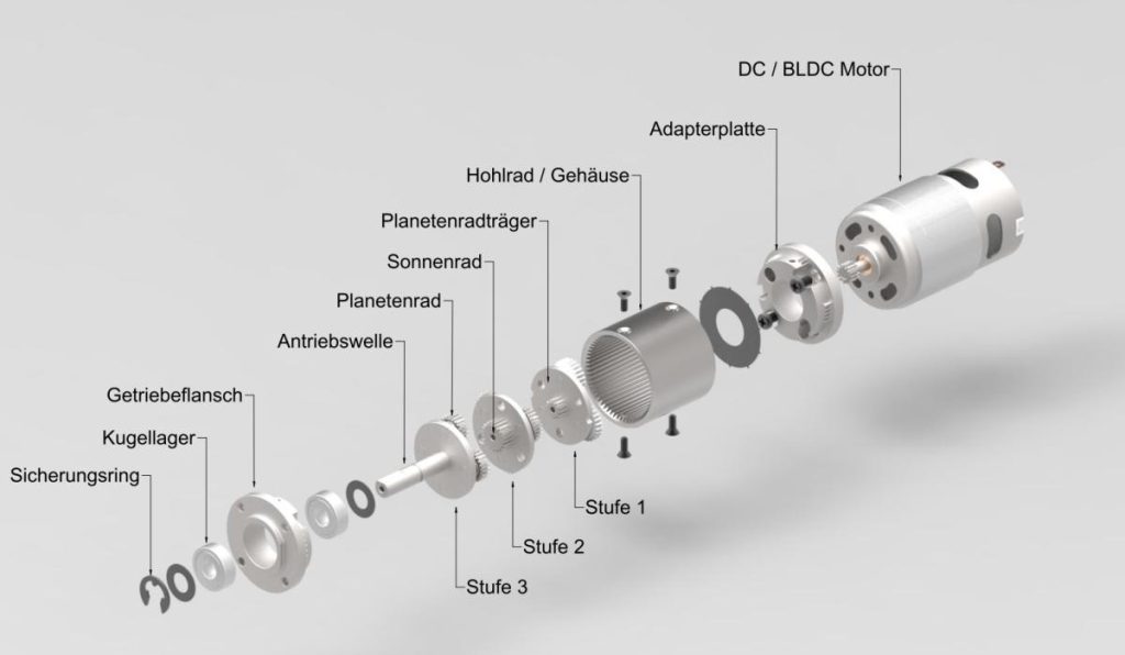
You should choose a planetary gearbox design when your application demands high torque density, precision, and efficiency within a compact spatial envelope. This mechanical system distributes physical loads evenly across multiple gear teeth to prevent premature wear. Integrating this with a motor gearbox ensures your system manages heavy peak shocks without physical deflection.
Understanding the Sun and Planet Set
The planetary design consists of a central sun gear surrounded by multiple orbiting planet gears, all enclosed within an outer ring gear. This unique layout means the load is split across three or four contact points simultaneously.
- Sun gear: Positioned at the center to accept the high-speed input.
- Planet gears: Orbit the sun to divide and transmit the torsional load.
How so? By dividing the forces, the structural load on each individual gear tooth is significantly reduced.
Benefits of Planetary DC Motors
Utilizing a premium planetary gearbox dc motor allows high continuous duty power transmission with minimal mechanical backlash. They represent the gold standard for demanding robotic and automated systems.
- Robotic joints: Zero-drift precision positioning under heavy static loads.
- 3D printing drives: Smooth, high-torque filament extrusion control.
- Medical actuators: Highly quiet surgical table position adjustments.
| Attribute | Planetary System | Standard Gearbox | |
|---|---|---|---|
| Torque Density | Outstanding | Moderate | |
| Backlash Control | Extremely Precise | Standard | |
| Component Life | Long-Lasting | Variable |
The data confirms that planetary gearheads provide superior torque capability and precision control compared to conventional single-mesh gearboxes. Key Takeaway: Planetary systems maximize mechanical life and load handling by spreading structural stress across multiple contact teeth. Why does this happen?
When Should You Use a Worm Gearbox?
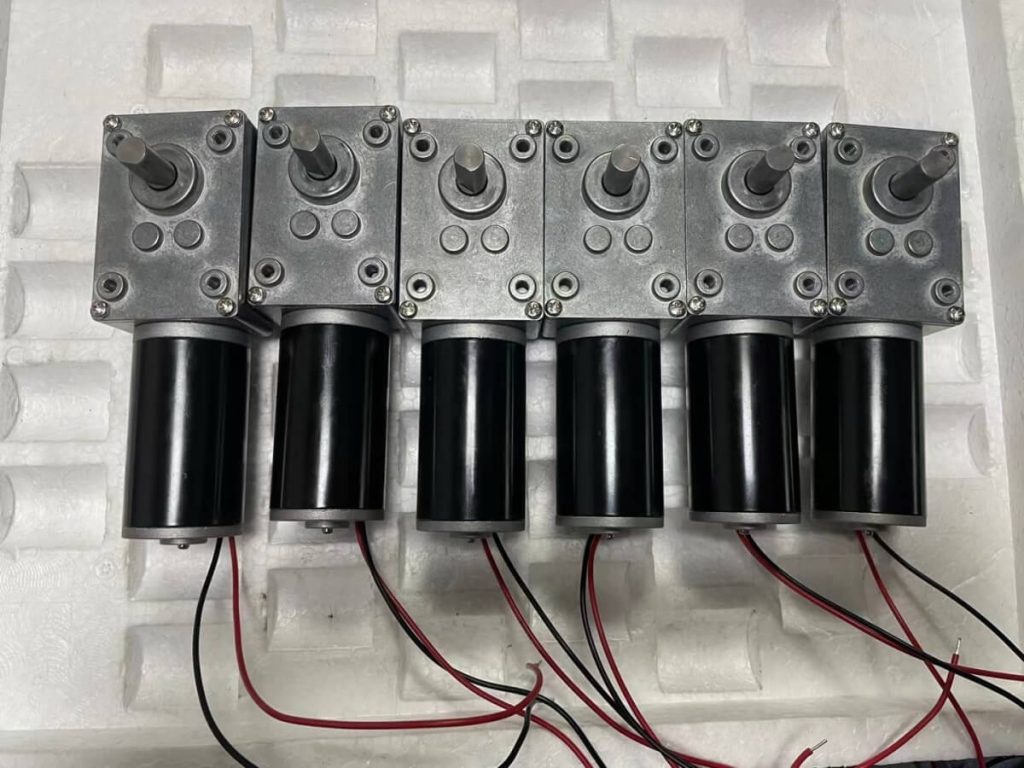
You should use a worm gearbox when your system requires self-locking safety capabilities and a substantial right-angle speed reduction in a very tight footprint. Integrating a worm motor gearbox prevents the output shaft from back-driving the motor when power is disconnected. This eliminates the need for expensive secondary braking systems.
The Mechanics of Sliding Contact
Worm gearboxes consist of a screw-like worm shaft that meshes with a perpendicular worm wheel. This sliding contact mechanism absorbs heavy shock loads while operating with incredible smoothness.
- Sliding contact: Dampens operational noise and acts as a shock absorber.
- Right-angle output: Translates motor force 90 degrees to fit tight chassis.
What are the benefits? The sliding contact model provides unparalleled smoothness during continuous runs.
Advantages of Worm Gear DC Motors
A specialized worm gearbox dc motor is the perfect choice for conveyor drives and elevator mechanisms. They eliminate the need for secondary mechanical braking systems.
- Door locks: Automated gate and secure window locks that resist forced entry.
- Conveyor lines: Stop-and-go packaging belts that must hold static positions.
- Adjustable lifts: Medical beds and patient lifts requiring absolute fall safety.
| Feature | Worm Gearbox | Conventional Helical | |
|---|---|---|---|
| Backdrive Ability | Non-backdrivable (Self-locking) | Easily backdrivable | |
| Shaft Angle | 90-degree right angle | Parallel or Coaxial | |
| Peak Efficiency | 50% – 75% | 90% – 98% |
This clear trade-off shows that worm drives sacrifice overall efficiency to achieve complete mechanical safety and high-ratio reductions. Key Takeaway: Worm gearboxes deliver unmatched safety via self-locking functions, but they trade away some mechanical efficiency due to friction. The bottom line:
What Makes Helical Gearboxes Different?
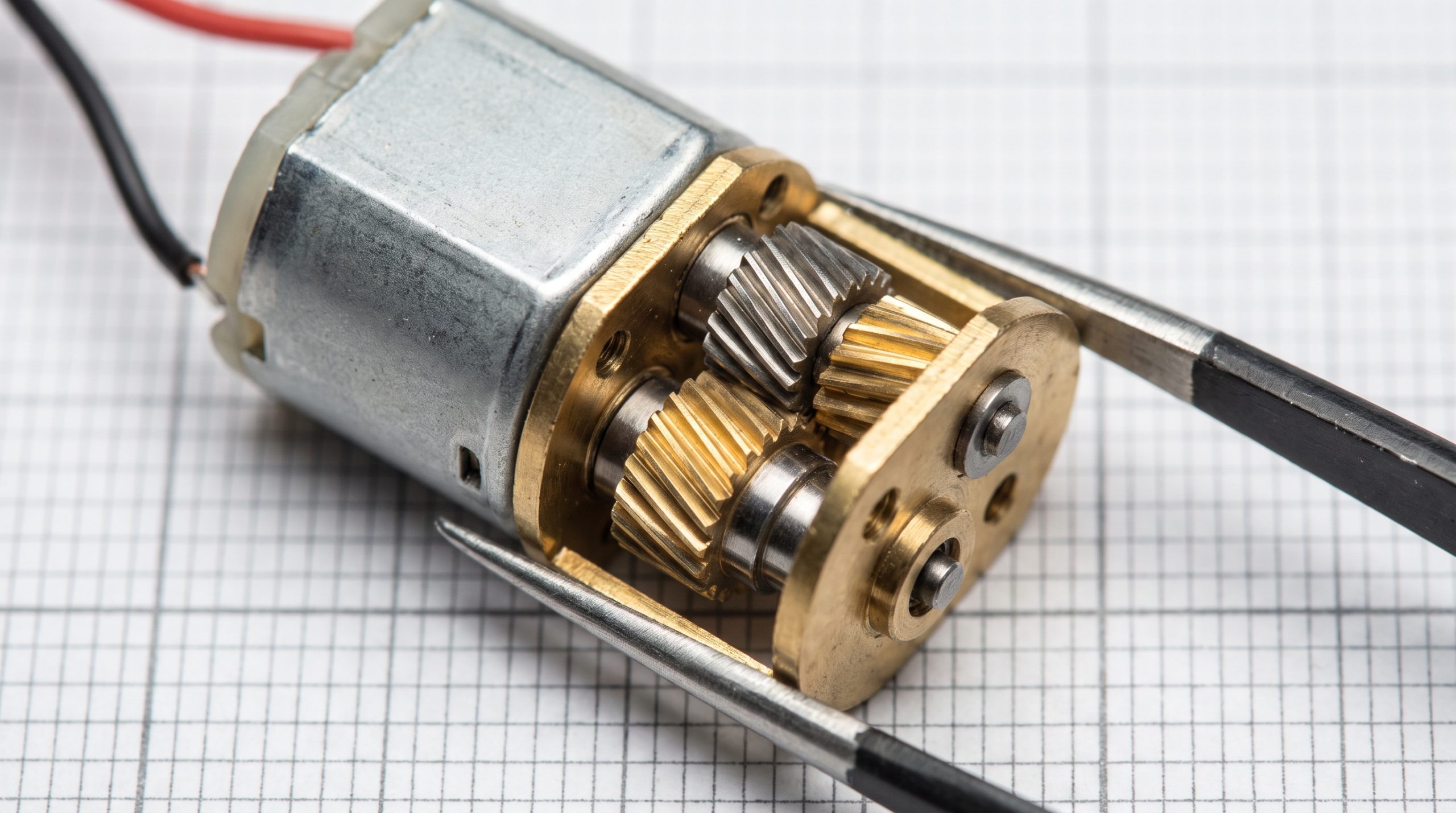
Helical gearboxes are different because their teeth are cut at an angle to the shaft, allowing them to engage gradually and operate far more quietly than straight-cut spur gears. This angled engagement ensures multiple teeth share the load at any given moment. Selecting a helical motor gearbox is ideal for quiet high-speed industrial environments.
Continuous Meshing and Low Noise
As helical gears rotate, the contact between teeth moves smoothly from one end of the tooth to the other. This continuous tooth engagement minimizes vibrations and eliminates high-frequency operational hums.
- Angled teeth: Gradual contact minimizes sudden impacts between gear sets.
- High-speed capacity: Smooth transmission permits high continuous RPM.
But there is a twist. This unique angled geometry introduces mechanical forces that require special compensation.
Managing Axial Thrust Loads
The angled teeth of helical gearboxes generate thrust loads along the shaft axis during operation. Because of this, high-quality thrust bearings must be integrated into the housing to manage these axial forces.
- Thrust bearings: Counteract axial forces generated along the shaft.
- High load: Multi-tooth contact distributes structural strain effectively.
| Feature | Helical Design | Spur Design | |
|---|---|---|---|
| Noise Emission | Extremely Low | Moderate to High | |
| Load Capacity | High (Multi-tooth contact) | Low (Single-tooth contact) | |
| Thrust Forces | Generated (Requires bearings) | None |
As shown above, helical gears excel in quietness and load sharing, but require robust internal bearings to manage the axial thrust they create. Key Takeaway: Helical gearboxes provide whisper-quiet operation and high load capacities, making them ideal for high-speed continuous industrial runs. How does that work?
How Do Flat Gearboxes Save Space?
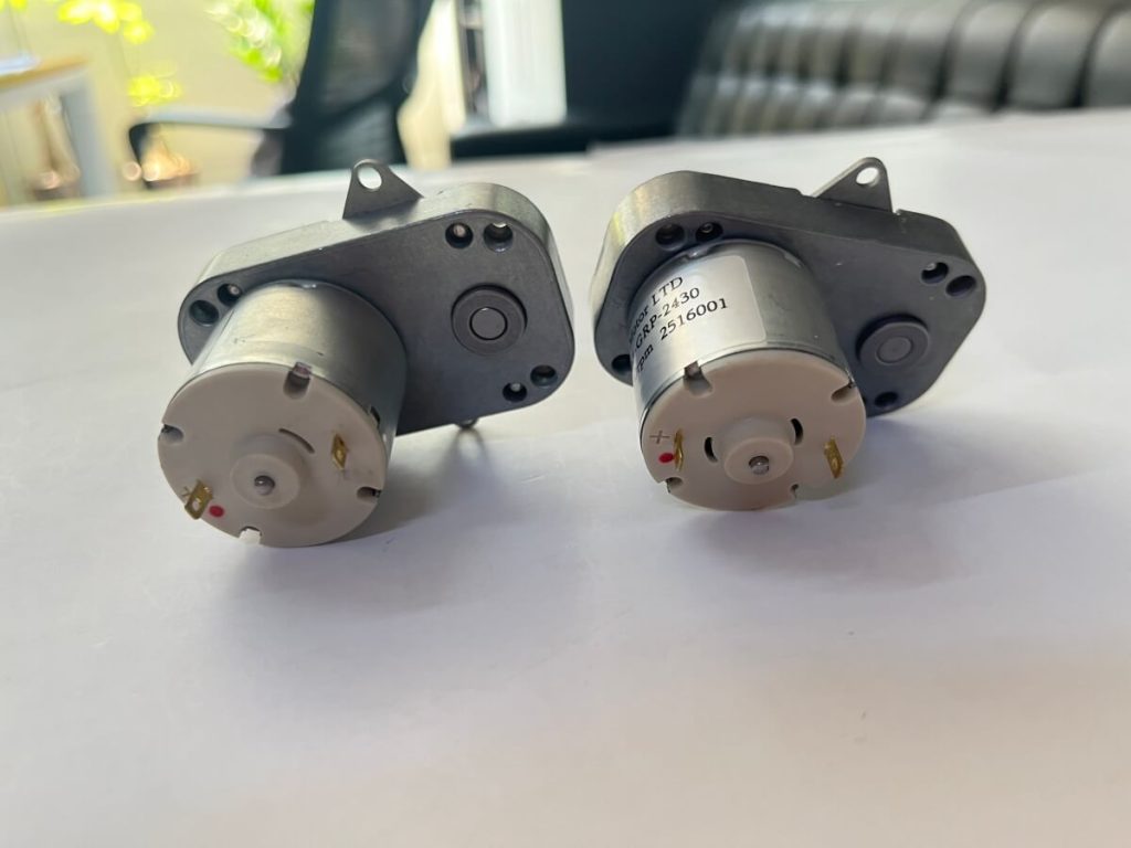
Flat gearboxes save space by utilizing flat-profile, parallel-shaft gear arrangements that fit into extremely narrow chassis envelopes. Utilizing a flat motor gearbox lets B2B product developers shrink the depth of their mechanical enclosures without sacrificing torque output. This design maximizes packaging density inside smart appliances.
Maximizing Torque in Tight Profiles
A flat gearbox arranges gears in a coplanar fashion, spreading the mechanical reduction horizontally rather than axially. This allows the overall motor assembly to remain incredibly thin.
- Coplanar gears: Spreads torque horizontally across parallel shafts.
- Reduced depth: Eliminates the protruding tail common in inline designs.
Why does this matter? By shifting the gear layout laterally, developers can design much shallower equipment cabinets.
Implementing Flat Gear DC Motors
Specifying a flat flat gearbox dc motor is highly beneficial for wall-mounted devices or automated guided vehicles (AGVs). They allow designers to tuck the drivetrain flat against the machine walls.
- Access barriers: Flush-mount turnstiles and automatic subway ticket gates.
- AGV drives: Low-profile automated warehouse carts navigating under racks.
- Smart shutters: Slim-line architectural shade and shutter controllers.
| Profile Parameter | Flat Gearbox | Coaxial Planetary | |
|---|---|---|---|
| Axial Length | Extremely Short | Longer/Deep | |
| Width/Height | Wider Footprint | Ultra-Compact Circular | |
| Installation Style | Flush Wall Mount | Centered Inline |
This layout details how flat gearheads trade transverse space for a significantly reduced axial length, making flush mounting highly practical. Key Takeaway: Flat-profile gearboxes are the ultimate B2B choice when axial length is your tightest engineering bottleneck. Are you wondering why?
Why Do Brushless Motors Need Gears?
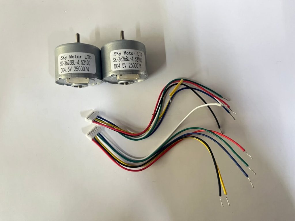
Brushless motors need gears because they are naturally designed to run at exceptionally high speeds where they are most efficient, requiring mechanical reduction to perform heavy-duty, low-speed tasks. Adding a physical motor gearbox matches this high-efficiency speed to realistic load demands. This dynamic pairing prevents the motor from stalling while saving energy.
High Efficiency at High Velocities
Brushless DC (BLDC) motors achieve their highest power-to-weight ratios when spinning rapidly. Operating them directly at very low speeds reduces their efficiency and can cause thermal issues.
- High speed: Optimal BLDC performance occurs at high RPM.
- Heat mitigation: Running slow under high load generates extreme thermal stress.
Here is the kicker: A gearhead allows the motor to maintain its peak speed while outputting slower, safer drive.
Leveraging Brushless Gear Motors
Combining a high-torque gearbox with a premium brushless motor creates a robust, low-maintenance motion control solution. This combination offers long operational lifespans because there are no carbon brushes to wear down.
- Continuous pumps: Long-running industrial chemical and coolant pumps.
- Industrial conveyors: Constant heavy-load freight and parcel sorting systems.
- AGV driving wheels: Reliable, spark-free locomotion for hazardous cleanrooms.
| Metric | Geared BLDC System | Direct Drive BLDC | |
|---|---|---|---|
| Low-Speed Torque | High and Stable | Limited/Stalls Easily | |
| System Efficiency | Optimized | Poor at low RPM | |
| Maintenance Needs | Virtually Zero | Extremely Low |
The data illustrates that adding a gearbox allows BLDC motors to maintain peak efficiency while delivering the high torque needed at lower speeds. Key Takeaway: Pairing BLDC motors with gearheads delivers unmatched longevity and efficiency across a massive range of operating speeds. What is the result?
How Do Encoders Improve Gear Performance?
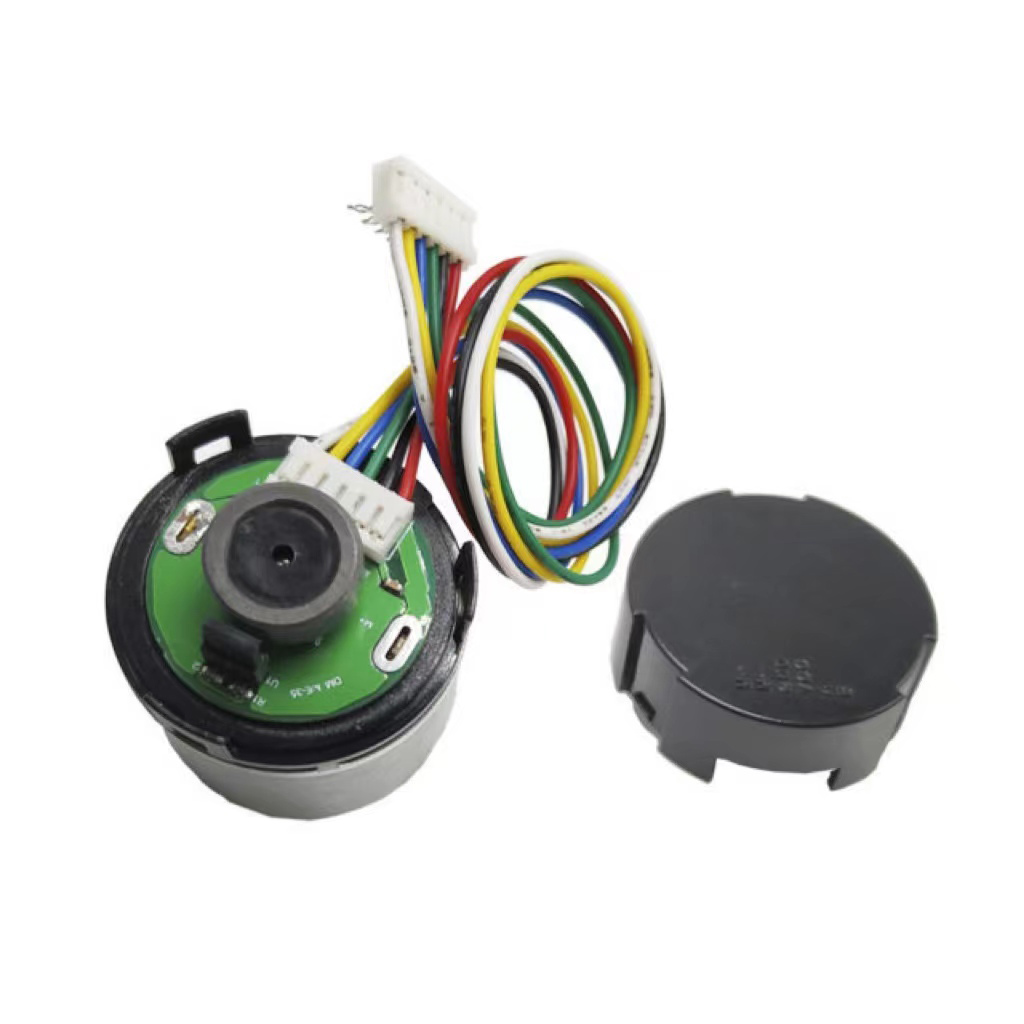
Encoders improve gear performance by providing real-time rotational feedback to the motor controller, allowing for precise speed adjustments and closed-loop positioning. Integrating a high-precision motor gearbox with an encoder ensures that gear backlash does not compromise positioning accuracy. This closed-loop feedback loop is vital for delicate automation tasks.
Closing the Control Loop
Without feedback, a motor controller cannot compensate for physical load changes or slight mechanical slippage inside the gear stages. Encoders track exact rotor position to make instantaneous current corrections.
- Real-time tracking: Prevents positional drift under fluctuating loads.
- Dynamic speed correction: Adjusts current on the fly to maintain constant RPM.
Think it stops there? This integration eliminates accumulative errors over long operational duty cycles.
Precision with Hall Sensor Encoders
A gear motor equipped with a hall sensor encoder tracks rotational steps via magnetic pulses. This enables micron-level movement repeatability even under fluctuating load conditions.
- Pick-and-place arms: Highly accurate parts placement on high-speed lines.
- Dosing pumps: Accurate fluid delivery volume control in medical labs.
- CNC feed drives: Micro-stepping physical feed control for precise milling.
| System Type | Position Feedback | Backlash Compensation | |
|---|---|---|---|
| Geared + Encoder | Continuous Closed-Loop | Highly Manageable | |
| Open-Loop Geared | None (Assumed Position) | High risk of error |
This matrix shows that adding an encoder is crucial for applications where any deviation in output shaft position cannot be tolerated. Key Takeaway: Closed-loop encoder feedback compensates for natural mechanical tolerances within your gear trains, maximizing positioning precision. What is the impact?
How Do You Select the Perfect Gearbox?
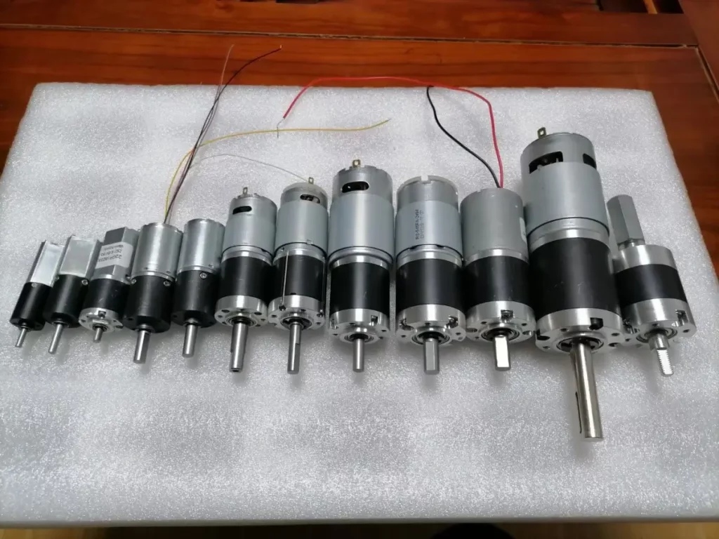
Selecting the perfect gearbox requires analyzing your torque requirements, speed limits, mounting space, axial/radial load limits, and backlash tolerances. Balancing these operational parameters ensures you avoid purchasing an over-engineered or under-powered motor gearbox. This careful calibration saves development time and reduces product unit cost.
Understanding Backlash and Back-Driving
Gearbox backlash is the clearance or play between mating gear teeth, while back-driving is the ability of an external load to rotate the gearbox backward from the output shaft. Understanding these two physical phenomena is critical when designing safe, bidirectional motion control systems.
- Backlash: Play between teeth that creates a small dead-angle during direction changes.
- Back-driving: Occurs easily in planetary gearheads, but is blocked in worm drives.
But is it really that simple? You must choose your gear structure based on whether you need back-drive safety or ultra-low backlash.
Defining Your Dynamic Load Profile
Calculate both your normal running torque and your peak startup torque. Ensure the gearbox’s structural rating can withstand repeated start-stop shock loads over thousands of hours.
- Torque matching: Map nominal operating torque against peak startup spikes.
- Input limitation: Verify maximum permissible input speed limits of the gear head.
- Load ratings: Calculate radial and axial load forces pushing against the output shaft.
| Selection Criteria | Focus Area | Impact of Miscalculation | |
|---|---|---|---|
| Torque Capacity | Mechanical Strength | Structural tooth failure | |
| Thermal Limits | Heat Dissipation | Lubricant breakdown | |
| Shaft Loading | Bearing Endurance | Rapid shaft deflection |
Careful evaluation of these pillars guarantees a long, maintenance-free operational life for your automated system. Key Takeaway: The most reliable system is achieved by co-designing the motor and gearbox together as a matched pair. Here is the real secret:
How Do You Resolve Common Gearbox Questions?
To resolve common gearbox questions, you must evaluate how specific design parameters affect efficiency, safety, and performance in your application. Selecting the right motor gearbox requires a clear understanding of torque and speed limitations. Below, we address some of the most frequent technical inquiries from B2B engineers.
What’s the best gearbox for a high-precision B2B robotics application?
Planetary gearboxes are the absolute premier option for precision robotics. These systems provide superior torque density and minimal backlash for complex multi-axis motion. They allow your automated systems to operate with supreme positional repeat accuracy.
Can I use a spur gearbox for continuous high-speed industrial applications?
No, spur gearboxes are poorly suited for high-speed, continuous-duty industrial lines. Their straight-cut teeth mesh one at a time, creating significant noise and vibration at high velocities. This rapid impact causes accelerated tooth wear and premature transmission failure.
How do I know if my system requires a self-locking worm gearbox?
Yes, your system requires a worm gearbox if you are lifting vertical loads or require safety-stop protection when power drops. The unique sliding contact between the screw and gear prevents gravity from back-driving the output. This eliminates the need for expensive secondary braking systems.
Can I mount a flat gearbox flush against an automated vehicle chassis?
Yes, you can easily mount a flat gearbox flush against any flat machine surface. Their parallel offset shafts distribute torque laterally rather than axially, keeping the overall gearbox profile incredibly thin. This layout is perfect for automated guided vehicles navigating tight warehouse aisles.
How do I know if a brushless motor needs a closed-loop encoder?
Yes, you should add an encoder if your application demands exact velocity matching or micron-level position control. Feedback compensates for gear play, allowing the drive controller to make instant positioning corrections. This prevents cumulative mechanical errors during complex movements.
Streamline Your Custom Drivetrain Solution Today
Building the perfect mechanical drive system doesn’t have to be a trial-and-error process. ISKY Motor has spent years engineering high-performance planetary, spur, worm, and flat gearbox assemblies tailored to demanding B2B applications worldwide. Our team of engineering experts will help you select, customize, and integrate the precise motor-gearbox configuration your design requires.
Are you ready to optimize your application’s speed, torque, and efficiency? Contact our engineering sales team to contact us today and request a custom quote for your next project.