
The torque-speed characteristics of DC gear motors represent the inverse linear relationship between mechanical load torque and output rotational speed under a constant input voltage. Designing high-precision automated systems often presents engineers with the critical challenge of selecting a drive mechanism that balances dynamic mechanical load fluctuations. If you select a motor with inadequate torque or speed capabilities, your automation system will suffer from continuous stalling, system inefficiencies, and catastrophic thermal failures in the field. To resolve this persistent engineering bottleneck, integrating a robust dc motor with gear provides the exact speed-reduction and torque-multiplication profile your application demands.
Understanding how these electromechanical components interact under dynamic load allows B2B procurement teams and system integrators to make informed technical decisions. Let us explore the engineering dynamics of these systems to optimize your product’s performance and operational lifetime.
Why Do Miniature DC Gear Motors Dominate Modern Engineering?
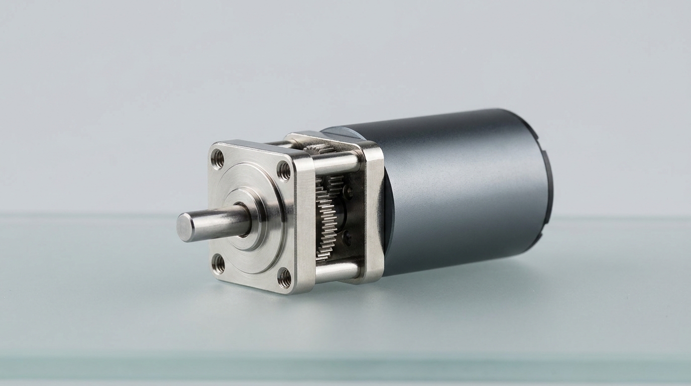
Miniature DC gear motors dominate modern engineering because they offer unmatched torque density, precise speed regulation, and compact packaging that fits seamlessly into constrained automated spaces. By integrating a miniature dc motor with gear, B2B OEMs can achieve low-speed high-torque operation without relying on bulky external belt systems or oversized frame sizes. This structural consolidation streamlines manufacturing supply chains and reduces the total bill of materials for industrial equipment.
Furthermore, the standardized mounting layouts simplify technical integration across diverse machine configurations. This flexibility makes them highly suitable for rapidly evolving industrial architectures.
1.1 What Makes Their Compact Design So Powerful?
Think about this: as automation architectures shrink, space becomes the ultimate premium, demanding that drive systems pack maximum power into minimal footprints. By merging the motor and gear train into a single, cohesive unit, designers eliminate the alignment issues common with separate components. This unified structural configuration increases torsional rigidity while eliminating mechanical backlash that plagues larger assemblies. Consequently, industrial designs benefit from minimized weight profiles and significantly improved dynamic response times.
Moreover, the reduction in physical size does not compromise mechanical reliability. Specialized manufacturing tolerances ensure that the integrated components operate in complete harmony under variable loads.
1.2 How Do They Deliver High Torque in Small Spaces?
To deliver immense force within small envelopes, miniature systems rely on advanced mechanical gear arrangements that split the torque load across multiple contact points. High-precision manufacturing ensures that the teeth engage with minimal friction loss, optimizing power transfer. Key features that facilitate this power density include:
- High-ratio gearing: Small input stages drive larger output wheels to multiply rotational forces.
- Optimized tooth profiles: Specialized involute profiles maximize surface contact and load distribution.
- Premium metallurgy: Hardened steel or engineered plastics absorb operational shock loads without wearing down.
Key Takeaway: Selecting miniature gear systems allows B2B OEMs to maximize torque output while maintaining a compact physical footprint, ensuring reliable and energy-efficient operations.
| Feature | Miniature Gear Motor | Standard DC Motor | |
|---|---|---|---|
| Torque Density | Extremely High | Low to Moderate | |
| Footprint Volume | Ultra-Compact | Large and Bulky | |
| Speed Regulation | Highly Precise | Hard to Control under Load |
The data clearly illustrates how integrating speed-reduction gearheads elevates basic DC motor performance to meet demanding precision standards.
How Does Torque Affect the Speed of a DC Gear Motor?
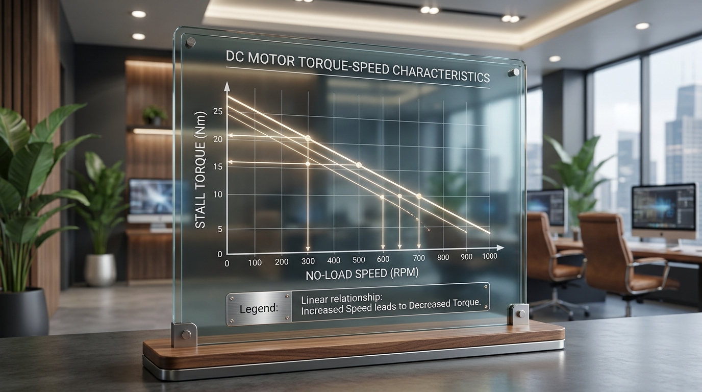
Torque affects the speed of a DC gear motor in an inversely proportional manner, where increasing the mechanical load causes a linear reduction in rotational speed. Under a constant operating voltage, as the mechanical resistance on the output shaft rises, the winding current increases, causing the rotational velocity to drop. Utilizing a high-performance dc motor with gear ensures that this speed drop is controlled, allowing the machine to sustain high loads before reaching its physical stall limit.
Understanding this performance curve is crucial for engineers who must select a motor that operates within its safe continuous limits. Working near the stall threshold will lead to thermal overload and eventual catastrophic failure.
2.1 What Is the Mathematical Inverse Relationship?
Here is why this matters: understanding the linear equation that governs torque and speed allows B2B engineers to predict system performance under varying load profiles. The linear relationship is mathematically defined by the standard equation linking torque directly to operational speed. As the operating speed decreases, the back-electromotive force drops, allowing more current to flow and generate the required torque. This self-regulating electro-mechanical behavior forms the core foundation of direct current motion control.
Mechanical engineers use these calculations to map duty cycles against the motor’s power bandwidth. This mathematical modeling minimizes engineering errors during the early prototyping phases of development.
2.2 Can We Predict Stall Torque and No-Load Speed?
Yes, engineers can accurately predict both stall torque and no-load speed by analyzing the motor’s electrical specifications and gearbox efficiency ratings. The no-load speed defines the maximum rotational velocity of the shaft with zero load, while stall torque represents the maximum holding power when speed drops to zero. Standard predictability methods involve:
- Extrapolating current draw: Measuring current at no-load and stall conditions establishes the slope of the curve.
- Applying gear ratio multipliers: Factoring in the gear ratio and gearbox efficiency adjustments to calculate the final output shaft parameters.
- Voltage scaling: Modifying input voltage shifts the entire curve parallel, changing the absolute values proportionally.
Key Takeaway: Accurate prediction of stall torque and no-load thresholds prevents drive stalling and system failures, allowing for safe continuous-duty operations in automated environments.
| Parameter | Stall Torque | No-Load Speed | |
|---|---|---|---|
| Definition | Maximum torque at zero rotational speed | Maximum speed at zero external load | |
| Current Level | Maximum (Stall Current) | Minimum (No-Load Current) | |
| B2B Impact | Determines maximum startup and load capacity | Establishes the fast-cycle return speeds |
This comparative breakdown outlines the operational boundaries that define the linear working window of any direct current geared drive.
How Do Gear Ratios Redefine Motor Speed and Torque Output?
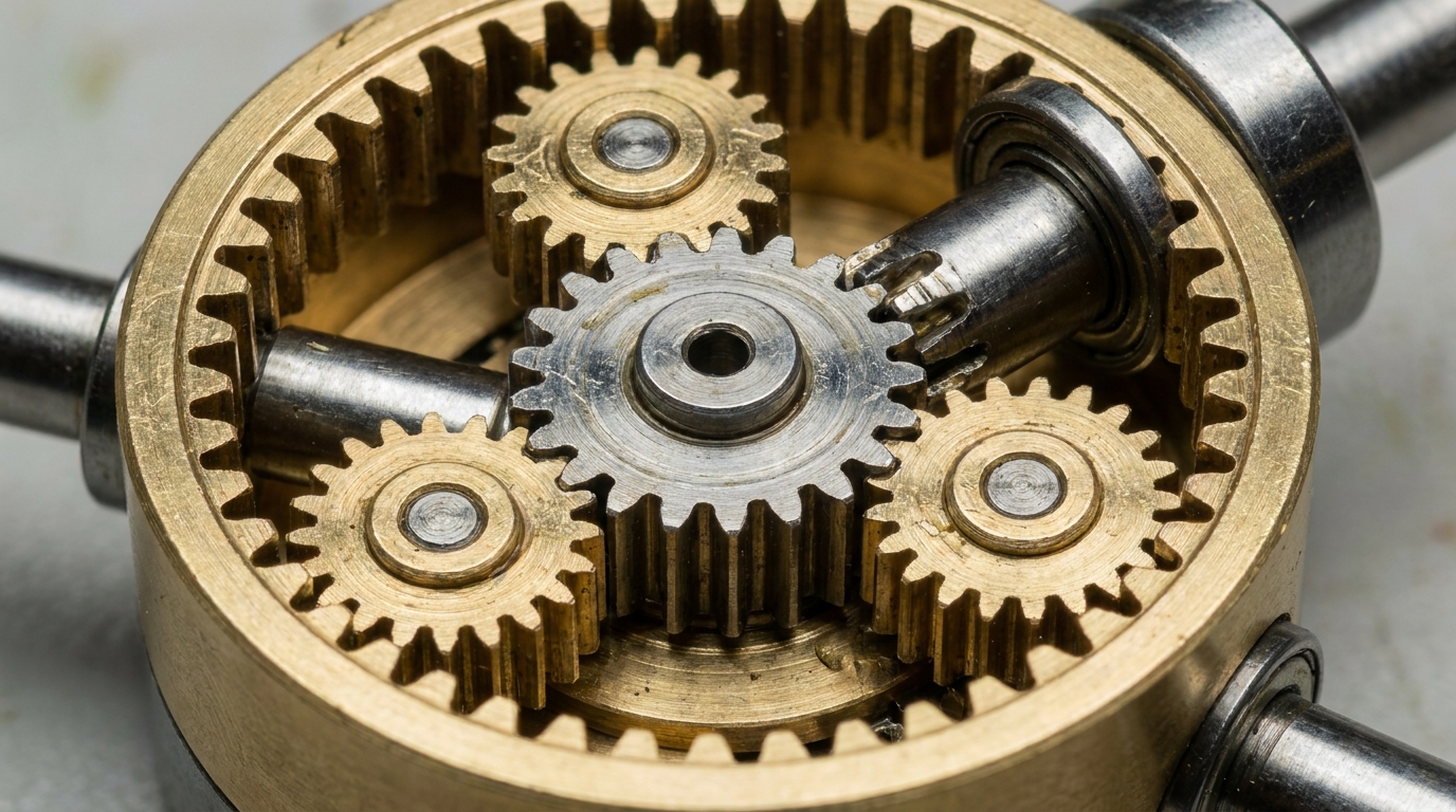
Gear ratios redefine motor speed and torque output by acting as a mechanical multiplier that proportionally reduces speed while multiplying the output torque. When a high-speed, low-torque motor is coupled with an appropriate gearhead, it converts rotational velocity into usable force. Choosing the correct gear ratio for a dc motor with gear is critical to achieving the perfect operational balance required for specialized B2B industrial projects.
High gear ratios yield high output force but require the motor rotor to spin rapidly, increasing wear and energy consumption. Achieving equilibrium between these parameters is the hallmark of professional mechanical system design.
3.1 How Does Mechanical Advantage Multiply Force?
The truth is: mechanical advantage is the core mechanism that allows a small, high-speed rotor to drive heavy industrial mechanisms. By transmitting rotational force through a series of interlocking gear teeth of varying diameters, the output shaft experiences a torque boost proportional to the gear ratio. This allows engineers to use smaller, more efficient motors to accomplish heavy-duty lifting or pulling tasks. Consequently, overall system energy consumption is reduced while mechanical efficiency is maximized under heavy loads.
The mechanical leverage gained from this configuration also acts as an external shock-absorber for the motor rotor. This mechanical isolation protects delicate electrical windings from direct rotational impacts.
3.2 Why Does Gear Efficiency Impact Overall Output?
While high gear ratios multiply torque, real-world mechanical friction, tooth sliding, and bearing resistance always consume a portion of the input power. Each gear stage introduces mechanical losses, meaning the actual output torque is always less than the theoretical calculated value. Understanding these efficiency limitations is essential because:
- Spur gears lose efficiency: They typically lose 1-2% of efficiency per gear stage due to simple mesh contact.
- Planetary gearheads redistribute loads: They maintain higher efficiency (typically 80-90%) under high-load multi-contact operations.
- Worm gears experience sliding friction: They have lower efficiency (often 40-60%) but offer unique self-locking characteristics.
Key Takeaway: Factoring in specific gearhead efficiencies during the design phase ensures that the chosen motor delivers sufficient torque to the actual load.
| Gear Type | Typical Efficiency Range | Primary Advantage | |
|---|---|---|---|
| Spur Gearbox | 85% – 95% | Cost-effective and simple design | |
| Planetary Gearbox | 80% – 90% | High torque density and radial load capacity | |
| Worm Gearbox | 40% – 60% | High ratio in a single stage, self-locking |
Evaluating these diverse gearhead technologies helps mechanical engineers optimize power transmission efficiency based on the application’s unique constraints.
Should You Choose Planetary or Spur Gearbox Motors?
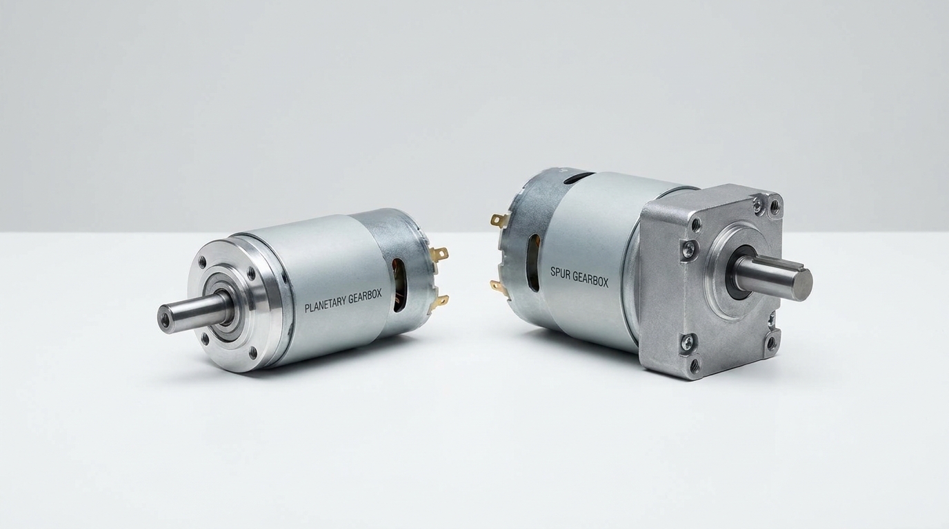
You should choose planetary gearbox motors for high-torque, space-constrained applications, and spur gearbox motors for cost-sensitive, lower-torque projects. Choosing the correct configuration of a dc motor with gear determines both the mechanical life and the financial viability of your automation solution. Evaluating the spatial limits and radial shaft loads of your machinery will immediately guide you toward the ideal gear arrangement.
While planetary designs excel in transmitting immense forces within circular footprints, spur designs offer straightforward, flat packaging options. Choosing between them requires balancing technical specs against commercial constraints.
4.1 When Is a Planetary Layout Superior?
Consider this fact: planetary gearboxes excel because they distribute mechanical loads across multiple planet gears simultaneously rather than relying on a single contact point. This load-sharing architecture dramatically increases the torque capacity and radial load limits of the output shaft within a very slim cylindrical profile. Engineers favor planetary systems for high-duty-cycle applications such as robotic joints, AGVs, and medical pump drives. The resulting inline shaft alignment also simplifies physical installation in tight tubular structures.
Furthermore, planetary systems maintain lower backlash profiles over extended operation cycles. This makes them highly suitable for precision positioning systems that require closed-loop feedback.
4.2 Are Spur Gearbox Motors Better for Cost-Sensitive Projects?
Yes, spur gearbox motors are highly suitable for cost-sensitive applications that require moderate torque and straightforward mechanical integration. Since spur gears are easier to manufacture and feature fewer internal components, they offer a highly competitive price point for high-volume consumer and industrial products. They are particularly beneficial due to:
- Low manufacturing complexity: Simple tooth manufacturing reduces tooling and material costs.
- Low friction losses: The straightforward gear arrangement yields higher single-stage efficiency at low speeds.
- Ease of maintenance: Accessible gear trains simplify inspection, lubrication, and replacement procedures.
Key Takeaway: Balancing performance requirements against budget limits helps engineers choose spur gears for cost efficiency and planetary gears for heavy-duty torque applications.
| Characteristic | Planetary Gearbox | Spur Gearbox | |
|---|---|---|---|
| Torque Capacity | Extremely High | Moderate | |
| Backlash Level | Low (High Precision) | Moderate | |
| Manufacturing Cost | Premium | Cost-Effective |
This comparative breakdown helps design teams select the appropriate gearbox topology to optimize both mechanical performance and unit economics.
Why Are Brushless DC Gear Motors the Future of Precision?
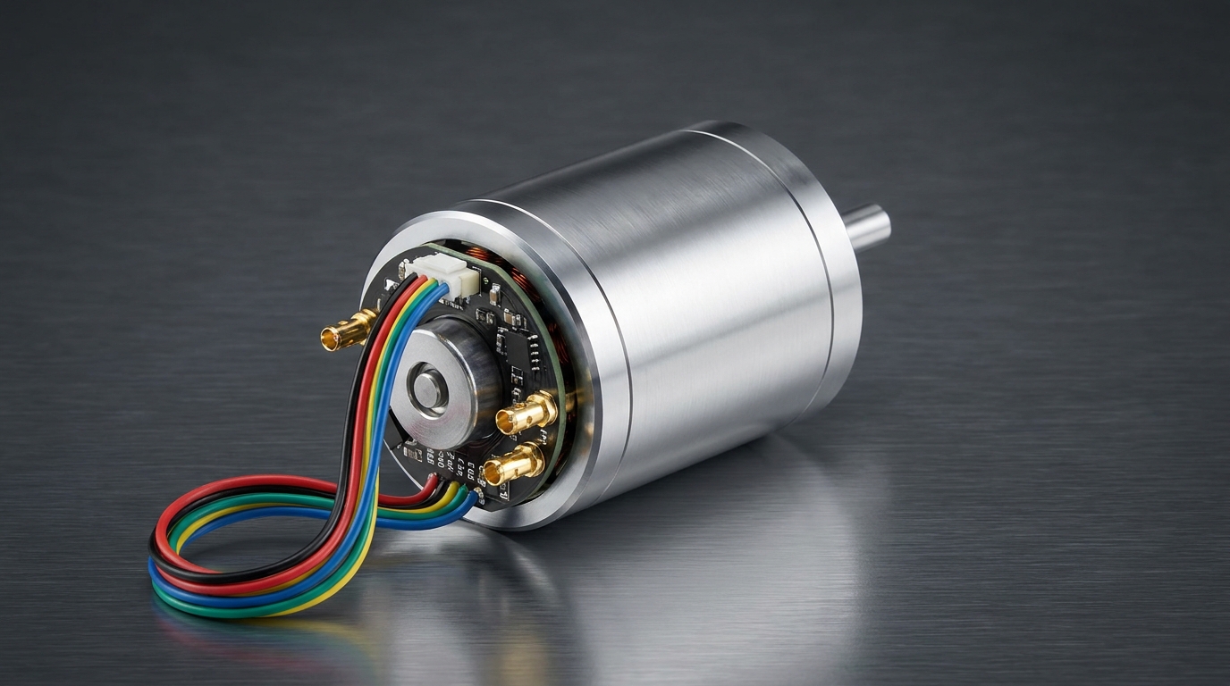
Brushless DC gear motors represent the future of precision because they eliminate mechanical brushes, which drastically reduces wear while allowing for exceptionally high speed-control accuracy. By upgrading to a brushless dc motor with gear, automated systems benefit from quieter operation, higher energy efficiency, and an extended operational lifetime. This technology represents the standard for modern high-end B2B medical, aerospace, and robotics platforms.
Precision motion control demands robust motor feedback loops that brushed legacy systems struggle to support over time. Transitioning to brushless systems protects long-term machinery assets from operational downtime.
5.1 How Do Electronic Commutators Eliminate Wear?
Electronic commutation replaces physical carbon brushes with solid-state driver electronics that switch current to the windings based on rotor position. Because there are no physical brushes dragging against a mechanical commutator, frictional wear, electrical arcing, and brush dust are completely eliminated. This frictionless rotation reduces internal thermal losses and increases overall motor efficiency to over 85% in many industrial configurations. Consequently, maintenance intervals are dramatically extended, which is a major advantage for sealed or remote installations.
Furthermore, electronic commutation reduces electromagnetic interference, safeguarding surrounding sensory equipment from signal degradation. This makes brushless designs ideal for modern smart factories and clinical laboratories.
5.2 What Role Do Hall Sensor Encoders Play in Feedback?
Hall sensor encoders are critical for modern closed-loop control systems, providing the driver electronics with high-precision feedback regarding rotor position, speed, and direction. By reading magnetic pole changes, the encoder translates physical rotation into clean digital pulses for real-time monitoring. The integration of Hall sensors offers distinct advantages:
- Precise positioning control: Enables micro-stepping and extremely accurate output shaft indexing.
- Dynamic speed correction: Allows the controller to adjust power output instantly when load levels change.
- High resistance to wear: Magnetic non-contact sensing ensures long-term reliability in harsh environments.
Key Takeaway: Brushless motors with integrated Hall encoders provide the precise closed-loop speed and position feedback necessary for complex robotic and automated machinery.
| Parameter | Brushed DC Gear Motor | Brushless (BLDC) Gear Motor | |
|---|---|---|---|
| Commutation Method | Mechanical Brushes | Electronic (Sensored/Sensorless) | |
| Maintenance Needs | Moderate to High | Zero (Virtually Maintenance-Free) | |
| Expected Lifespan | 2,000 – 5,000 Hours | 20,000+ Hours (Limited by bearings) |
This specification breakdown underscores why high-reliability applications are rapidly shifting away from legacy brushed platforms toward advanced brushless solutions.
How Do Thermal Dynamics Limit Torque-Speed Motor Performance?
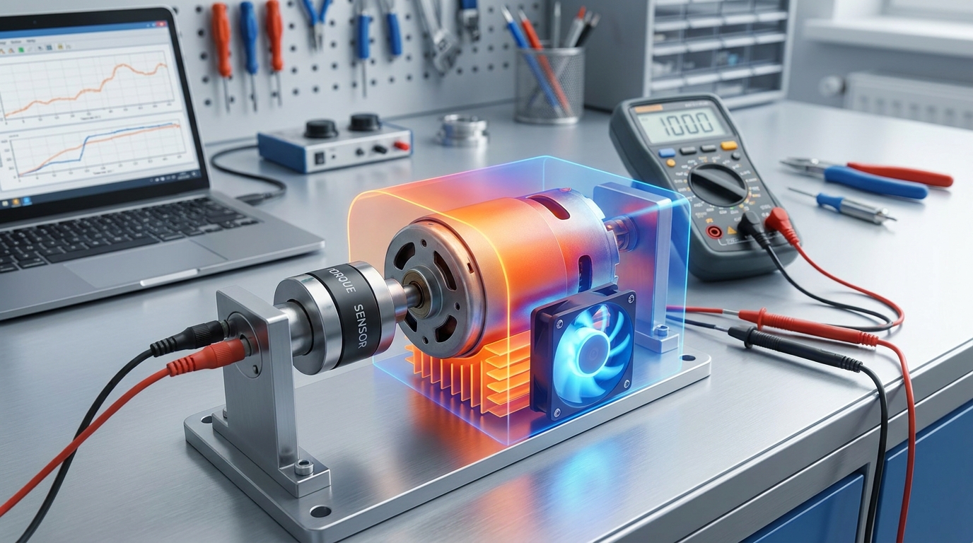
Thermal dynamics limit torque-speed motor performance by increasing electrical resistance in the windings, which reduces available current and diminishes output torque capabilities. As a dc motor with gear operates under heavy loads, internal copper losses and mechanical friction generate waste heat that must be safely dissipated. Left unchecked, excessive temperatures degrade the rotor’s permanent magnets and melt winding insulation, triggering complete motor failure.
Engineers must carefully evaluate duty cycles to ensure thermal equilibrium is reached far below critical material thresholds. Monitoring internal heat levels protects high-value industrial machinery assets from failure.
6.1 What Happens to Torque Output as Temperature Rises?
Let’s be honest: temperature is the silent enemy of maximum torque production in any electromechanical system. When the copper windings heat up, their electrical resistance increases, which naturally restricts the maximum current that can flow at a given supply voltage. Since output torque is directly proportional to current, the motor’s speed-torque curve shifts downward, diminishing stall torque and reducing efficiency. Furthermore, high heat weakens the magnetic flux density of permanent magnets, compounding the drop in overall performance.
This degradation cycle can cause the motor to run slower and hotter under identical load conditions. Eventually, this thermal runaway leads to complete breakdown if there is no safety cutoff in place.
6.2 How Do We Optimize Heat Dissipation Under Load?
Optimizing heat dissipation requires a multi-faceted thermal management approach that combines smart structural design with active or passive cooling mechanisms. Keeping the motor operating within its specified thermal class guarantees long-term performance stability. Effective thermal management techniques include:
- Aluminum heat sinking: Attaching finned heat sinks directly to the motor housing maximizes passive surface area.
- Forced air convection: Deploying external miniature fans across the housing to rapidly remove boundary-layer heat.
- Thermally conductive potting: Filling internal air gaps with high-conductivity epoxy to transfer heat away from windings.
Key Takeaway: Effective thermal management prevents torque degradation and preserves the structural integrity of internal windings during continuous high-load operations.
| Cooling Type | Thermal Dissipation Efficiency | System Integration Cost | |
|---|---|---|---|
| Passive Heat Sinks | Moderate | Low (Simple and Maintenance-free) | |
| Forced Air Cooling | High | Moderate (Requires active power) | |
| Liquid Cooling | Maximum | High (Complex plumbing and seals) |
This comparison assists engineers in implementing the appropriate thermal mitigation strategy based on operational duty cycles.
Why Does Lubrication Dictate the Lifespan of Your Gearbox?
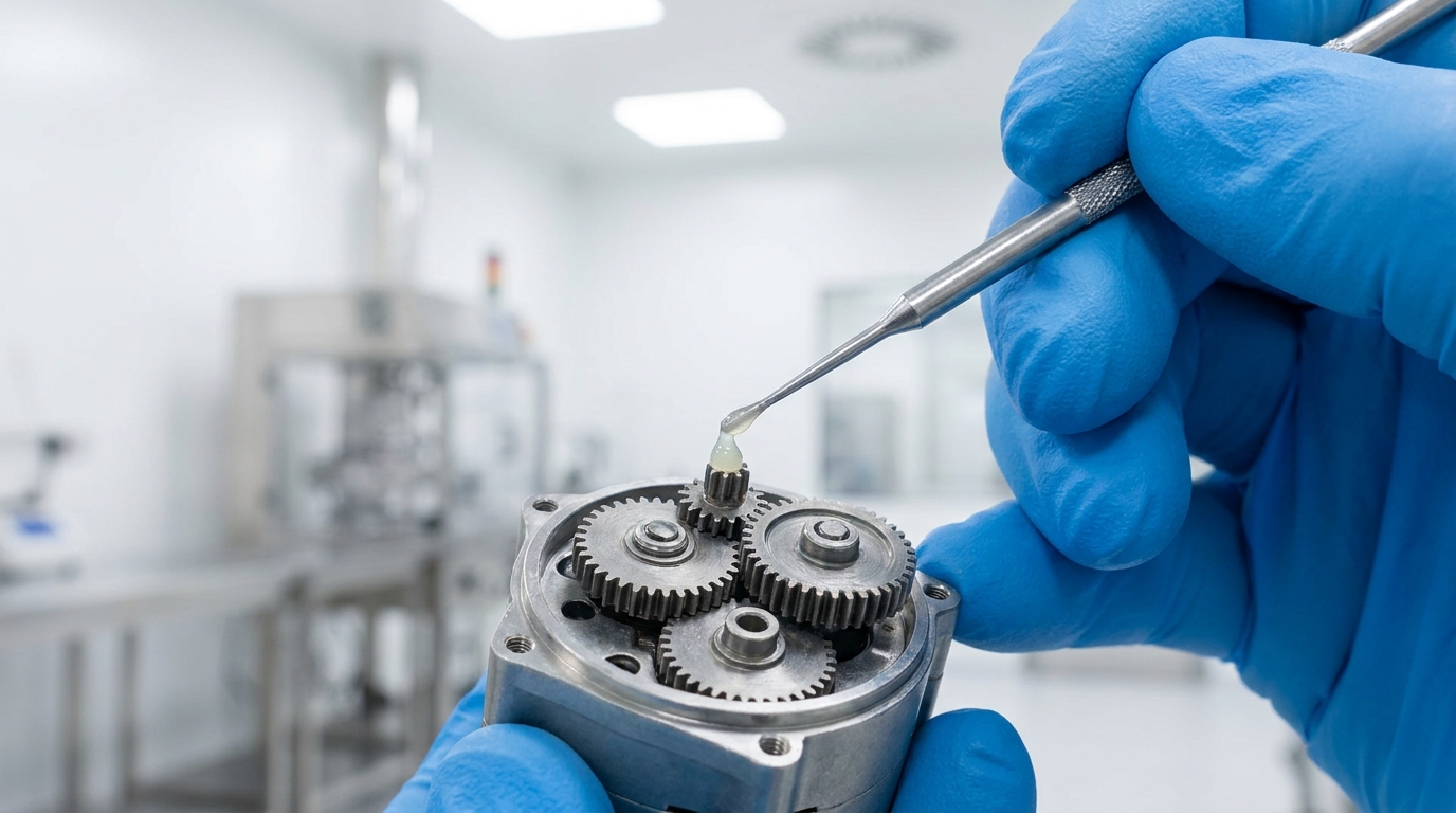
Lubrication dictates the lifespan of your gearbox by reducing direct metal-on-metal sliding friction, dissipating localized heat, and preventing premature gear tooth wear. In any compact dc motor with gear assembly, the high contact pressures of the tooth interfaces demand a continuous protective lubrication barrier. Choosing the wrong lubricant can lead to rapid pitting, increased backlash, and mechanical binding under normal operational loads.
Advanced grease formulations help seals stay intact, keeping dust and humidity out of the gearbox. This preventative barrier is key to long operational lifespans in tough industrial settings.
7.1 What Is the Role of High-Grade Synthetic Grease?
Think about this: high-grade synthetic grease does not merely lubricate the gears; it is a highly engineered chemical layer that prevents catastrophic wear. Formulated with advanced anti-wear additives and thickeners, synthetic grease maintains its viscous profile across extreme hot and cold temperature boundaries. This ensures the gearhead maintains low startup friction while preventing grease migration away from the fast-spinning teeth. Additionally, synthetic compounds resist shear breakdown and oxidation, ensuring long-term structural stability over years of service.
Using synthetic lubricant reduces friction, which also lowers energy use during operation. This chemical improvement directly supports the energy efficiency goals of modern automated systems.
7.2 Can Improper Lubrication Cause Mechanical Failure?
Yes, improper lubrication is one of the leading causes of premature gearbox failures in modern automated machinery. Using low-grade greases or incorrect viscosity levels can result in lubrication starvation at high tooth contact points, initiating severe micro-pitting and tooth breakage. Common failure modes stemming from poor lubrication practices include:
- Dry running and abrasion: Direct metal contact shears off microscopic steel particles, accelerating component wear.
- Thermal runaway: High friction elevates internal gear temperature, causing the grease to liquify and leak out.
- Lubricant gumming: Incompatible grease mixtures degrade into a sticky paste that increases mechanical drag and stalls the motor.
Key Takeaway: Utilizing premium, application-specific synthetic lubricants guarantees optimal torque transfer efficiency and maximizes the physical lifespan of your gear motors.
| Lubricant Type | Temperature Range | Lifespan Effect | |
|---|---|---|---|
| Mineral-Based Grease | Narrow (-10°C to 80°C) | Moderate (Requires periodic replacement) | |
| Synthetic Specialty | Wide (-40°C to 150°C) | Excellent (Lifetime lubrication sealed) | |
| Fluorinated (PFPE) | Extreme (-60°C to 250°C) | Maximum (Designed for vacuum & cleanrooms) |
Understanding these chemical differences allows B2B procurement teams to select the exact lubrication standard required for their specific environment.
How Do Engineers Accurately Measure Torque-Speed Curves?
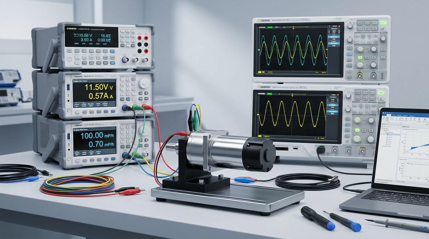
Engineers accurately measure torque-speed curves by utilizing specialized dynamometers and high-precision torque sensors that capture electrical input and mechanical output concurrently. To guarantee the real-world performance of a custom dc motor with gear , laboratory testing must subject the motor to a full spectrum of mechanical load profiles. This empirical verification confirms that the motor’s actual output aligns perfectly with calculated theoretical curves.
Standardizing these dynamic measurements across multiple production batches ensures high consistency in quality. This strict quality control prevents performance variations when the final product is shipped to global clients.
8.1 What Instruments Are Essential for Lab Verification?
In the engineering lab: raw power metrics are meaningless without high-precision measurement instruments to validate motor capabilities. Essential equipment includes precision programmable power supplies, digital oscilloscopes, current probes, and high-accuracy optical tachometers. Together, these tools capture dynamic voltage fluctuations, winding current draw, and rotational speed changes in real time. This complete electrical and mechanical dataset allows engineers to plot the exact efficiency curves of the motor-gearbox assembly.
High-accuracy sensors must be calibrated regularly to eliminate reading errors. This precision ensures that the test results remain highly repeatable across different laboratories.
8.2 How Do Dynamometers Capture Real-Time Performance Data?
Dynamometers capture real-time performance data by applying a controlled, adjustable mechanical load to the motor’s output shaft while recording its rotational speed. By stepping the load from a completely free-running state down to a stall condition, the testing system maps the entire linear operating region. Advanced dynamometer testing processes typically incorporate:
- Hysteresis brakes: Provide smooth, repeatable load application independent of the operating speed.
- Torque transducers: Directly measure actual mechanical twisting force at the output shaft with high accuracy.
- Data acquisition software: Graphs torque, speed, efficiency, and current curves automatically for rapid analysis.
Key Takeaway: Implementing rigorous dynamometer verification processes ensures that the supplied gear motors meet performance guarantees before mass production starts.
| Test Configuration | Key Instrument Used | Measurement Objective | |
|---|---|---|---|
| No-Load Verification | Optical Tachometer | Verifies maximum speed and internal friction losses | |
| Continuous Load Test | Magnetic Powder Brake | Evaluates heat rise and nominal speed stability | |
| Stall Torque Test | Reaction Torque Sensor | Measures absolute structural and holding limits |
This analytical testing framework ensures that every mechanical drive operates reliably within its designed performance limits.
Where Are High-Torque Mini Gear Motors Used Today?
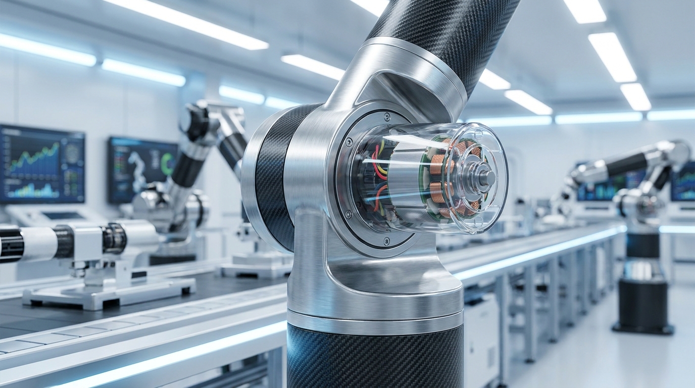
High-torque mini gear motors are used today in high-precision robotics, medical diagnostic devices, smart automated valves, and compact industrial actuators. Modern automation demands ultra-compact drive packages that can move physical loads with high accuracy and reliability. By standardizing on a premium dc motor with gear, OEM manufacturers can elevate the performance of complex mechanisms that require massive holding power.
As compact automation grows across various sectors, demand for high-durability gearboxes has expanded significantly. This growth drives manufacturers to continuously improve material designs.
9.1 How Do Robotic Joints Benefit from High Starting Torque?
Starting torque is the single most critical parameter when a robotic arm must lift a payload from a dead stop. Robotic joints require high starting torque to overcome structural inertia and static friction without jerking or slipping. Integrated miniature planetary gearheads deliver this necessary force boost while maintaining a slim physical profile that fits inside joint pivots. This allows multi-axis articulators to execute smooth, fluid movements with high mechanical precision and repeatability.
High holding torque also allows robotic limbs to remain stationary without continuous power consumption. This efficiency extends battery life in autonomous mobile robots.
9.2 Are Medical Devices Relying on Miniature Gear Motors?
Yes, high-precision medical devices rely heavily on miniature gear motors to drive peristaltic pumps, surgical robotics, and analytical laboratory instrumentation. In these life-critical applications, absolute reliability, whisper-quiet operation, and sterilizable construction are non-negotiable requirements. Medical-grade gear motor integration focuses on:
- Ultra-compact form factors: Fitting into handheld surgical instruments or bedside infusion pumps.
- High positioning accuracy: Ensuring precise medication dosing or micro-needle insertion depth.
- Low electromagnetic interference (EMI): Preventing electrical noise that could disrupt delicate diagnostic sensors.
Key Takeaway: The extreme precision and high safety margins of modern mini gear motors make them indispensable for clinical medical applications.
| Operational Metric | Robotic Joint Applications | Medical Device Applications | |
|---|---|---|---|
| Primary Focus | Maximum torque density and payload | Absolute safety, precision, and low noise | |
| Gear Type | Multi-stage planetary gearheads | High-precision spur or custom worm gears | |
| Feedback Type | High-resolution absolute encoder | Multi-channel Hall sensors |
Analyzing these diverse use cases highlights how mini gear motors serve as the vital mechanical muscle behind next-generation high-tech innovations.
How Can You Select the Perfect DC Gear Motor?
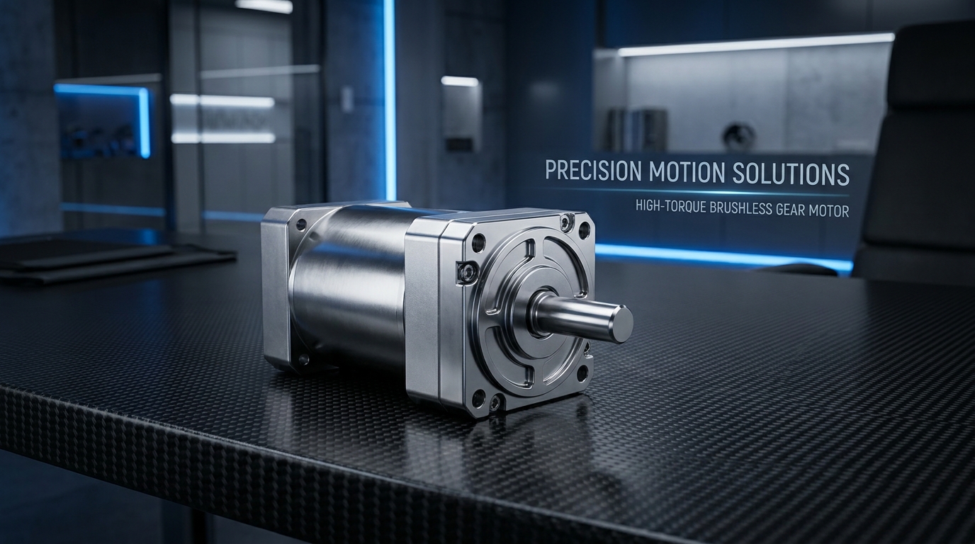
You can select the perfect DC gear motor by defining your application’s required output speed, torque profile, voltage limitations, and physical space constraints. Choosing the correct dc motor with gear ensures that your engineering project meets its long-term lifecycle targets without over-specifying and raising production costs. Collaborating with a professional manufacturer during the prototyping phase simplifies the entire technical selection process.
This selection step prevents mechanical failure under shock loads and reduces development time. Taking a structured approach helps design teams identify the right balance between cost and performance.
10.1 What Parameters Must You Check First?
You must first evaluate the nominal operating voltage, target shaft speed, and required continuous load torque. These baseline parameters define the core physical operating window and allow engineers to filter out mismatched frame sizes. Additionally, you must consider physical limitations such as shaft radial and axial forces, ambient temperature variations, and the maximum envelope volume available. Identifying these boundary constraints early prevents costly redesign cycles down the line.
Finding a motor that matches your power source avoids the need for complex conversion electronics. This step keeps the overall layout simple and reliable.
10.2 How Do You Match Load Requirements to Manufacturer Specs?
Matching load requirements involves analyzing the dynamic duty cycle of your application and selecting a motor with a rated continuous torque that exceeds your average load. If your system experiences peak loads, you must verify that the motor can handle short-duration overloads without overheating. To achieve a perfect technical match, follow these steps:
- Plot the load profile: Map torque and speed requirements across the entire operational sequence.
- Apply safety margins: Add a 20-30% cushion to your calculations to handle unexpected friction changes.
- Check gearbox efficiency: Adjust theoretical motor outputs to account for real-world gearing losses.
Key Takeaway: Rigorously matching dynamic load demands to manufacturer performance curves prevents field failures and maximizes the efficiency of your final automated assembly.
| Selection Step | Action Required | Objective | |
|---|---|---|---|
| 1. Torque Mapping | Calculate nominal and peak startup loads | Defines required gearbox strength | |
| 2. Speed Matching | Determine continuous operating RPM | Identifies the target gear ratio | |
| 3. Frame Evaluation | Match mounting footprints and shaft types | Guarantees seamless physical integration |
Following these systematic selection phases ensures a highly robust and cost-effective drive solution for your B2B application.
Conclusion & Strategic B2B Next Steps
Analyzing the intricate torque-speed characteristics of DC gear motors is the key to designing efficient, high-performance automated systems. By understanding the linear relationship between speed and torque, along with the mechanical advantages of various gearbox configurations, engineers can optimize system lifetime and reduce overall operational costs. Selecting premium components—from brushless motors to specialized planetary, worm, or spur gearboxes—ensures your equipment stands up to intense industrial duties.
As an industry-leading manufacturer of mini DC gear motors, iSky is fully equipped to support your custom engineering requirements. Our extensive product portfolio includes Brushless DC Motors, Planetary, Flat, Worm, and Spur Gearbox Motors, as well as high-precision Hall Sensor Encoders tailored to your specific application needs. Partner with our dedicated application engineering team to design, test, and optimize the perfect high-torque motion control solution for your next project, and contact us today to receive a customized quote.
Frequently Asked Questions
Can I run a DC gear motor at a higher voltage than its rated specification?
Yes, you can temporarily operate a motor at a higher voltage to achieve increased speed and torque outputs. However, this practice increases winding temperatures and brush wear, which can severely shorten the overall lifespan of the motor. Doing this continuously is not recommended.
What’s the best way to prevent my miniature DC gear motor from stalling under heavy shock loads?
The best approach is to select a planetary gearbox configuration with a high rated stall torque or integrate an electronic current-limiting controller. Planetary gearheads distribute high shock loads across multiple tooth contact points, reducing the risk of gear stripping. Additionally, a current limiter safely cuts power before the motor stalls and overheats.
How do I know if my application requires a brushless gear motor instead of a traditional brushed one?
You should choose a brushless gear motor if your application demands continuous maintenance-free operation, extremely high lifetimes, or high-speed precision. Brushed motors are suitable for low-duty cycle, cost-sensitive projects, but their mechanical brushes wear out over time. Brushless variants eliminate this failure point entirely while offering superior control.
Can I use a spur gearbox motor for high-torque robotic applications?
No, a standard spur gearbox motor is generally not recommended for heavy-duty, high-torque robotic joints due to its limited torque density and moderate radial load limits. Planetary gearboxes are the superior choice here because they handle massive forces by spreading the load across multiple gears. Spur gearboxes are much better suited for lighter, cost-sensitive applications.
How do I know if the lubrication inside my gearbox has started to break down?
You will notice a significant increase in operational noise, localized heat dissipation, and mechanical backlash as the lubricant degrades. When synthetic grease breaks down, it loses its ability to prevent metal-on-metal friction, which rapidly accelerates mechanical wear. Regular inspection prevents these issues from causing catastrophic drive failures.